Technical characteristics of a guillotine for metal. Sheet metal guillotines
Mechanical guillotine shears HA3121 and guillotine H3121 were created by employees of the design bureau of the Shimanovsky plant, which specializes in the manufacture of forging and pressing units.
1 Basic information about guillotine shears
Such equipment is understood as a cutting tool with an inclined type knife for transverse and longitudinal rectilinear cutting of metal sheets. Guillotine shears make it possible to process sheets not only by marking, but also by the side or back stop without marking.
The described devices are usually subdivided depending on the type of drive used on them into:
- hydraulic;
- crank (otherwise called mechanical).
Hydraulic equipment has more power, which can easily cope with steel sheets with a thickness of 6 centimeters. The cutting length of such scissors can exceed 8 meters. Mechanical devices are identical to hydraulic ones in a number of characteristics. At the same time, the former have a different drive system, assuming that the crank device provides movement of the blade in both the upper and lower directions.
The power of machines with a crank mechanism is lower than that of their hydraulic counterparts, therefore they are recommended for cutting workpieces with a thickness of 3 to 8 mm. But the metal processing speed of mechanical shears is higher (up to 56 cuts per minute versus 3-18 for "hydraulics").
In addition, guillotines have a different knife drive scheme (upper). There are cantilever shears with a rotary beam and machines with a straight knife stroke. The former are characterized by the fact that their upper knife moves due to the rotation of the beam around the centers located in the rear and on the side walls of the unit. Since the drive device of this very beam is located in similar installations inside the machine, they are compact in size.

In straight-running guillotines, the blade is connected to the frame. It is able to move down along straight guides due to the operation of two hydraulic cylinders or a crank mechanism. This design makes it possible to change the cutting angle of sheets of different thicknesses. Rotary machines this is not allowed. With them, the angle always remains the same as it was set by the manufacturer of the installation.
2 Guillotine shears H3121 - passport and characteristics
The passport of the machine contains the following technical data:
- maximum length of blanks for cutting - 200 cm;
- weight - 7000 kg;
- width (along the back stop) of the cut workpiece - 50 cm;
- brake - belt type;
- the number of edges for cutting - 4 pieces;
- engine power - 18.5 kW;
- the greatest cutting force - 50,000 kgf;
- the number of strokes of the cutting tool - from 40 or more per minute;
- clamping force - 2900 kg;
- distance between racks - 228.5 cm;
- knife inclination (angle) – 2°10".
Knives with a hardness of 54 to 58 HRC for the described guillotine are produced according to State standard 5950–73 from steel 6KhV2S, 5KhV2S, 6KhS. Their weight is 4.08 kilograms.

Scissors consist of the following main structural elements:
- drive unit;
- bed;
- lubrication system and electrical equipment;
- clamping and knife beam;
- shutdown clutch;
- protective grille and fences;
- back stop;
- table;
- drive shafts.
The bed is made in a welded form from sheet metal. Three couplers and a working table unite side racks of the machine in one piece. The lower cutting device (knife) is attached to the table. It allows you to set a specific gap value and adjust its value.

The drive of the guillotine is provided through a cylindrical gearbox with two steps and a V-belt drive by the engine. The knife beam of the device through the connecting rods receives movement (reciprocating) from the crankshaft. To balance it, there is a special mechanism of the spring principle of operation (it is called that - a balancer).
The coupling of the unit is made in a rigid form, it has an electromagnet and two veneers (rotary). Its design significantly reduces the operating costs of guillotine shears, as they operate without air supply.

To the desktop, the sheet that is cut is pressed against the rods. The principle of connecting rods with a knife beam allows you to increase the height of the knives by 2 centimeters. This function is very important, as it makes it possible to cut the sheet in the longitudinal direction.
3 Guillotine HA3121 - characteristics and description of scissors
Installation is performed with parameters that meet the requirements Specifications 1983 2-041-1068. This machine is used, made with an upper drive version, most often at the procurement sites of enterprises involved in mechanical engineering.
The knife bar is powered by a 17 kW motor. It is transmitted to the eccentric shaft through a brake clutch, transmission (V-belt), gearbox (has a cylindrical shape). After that, the rotation goes to the crank device and only then to the beam.
The table of the unit with the lower knives attached to it by means of screws rests on the racks. The latter are fastened together, forming a frame. The gap between the lower and upper knives is adjusted by moving the table horizontally.

The knife beam with knives (upper) is a L-shaped welded structure reinforced with stiffeners. Side and front stops attached to the table. The back stop is mounted on the back of the knife beam, it is installed with a screw mechanism.
The pneumatic brake clutch of the friction type is rigidly blocked, it is located on the drive shaft (at its left end). Reduction of dynamic loads and compensation of the weight of the beam (knife) is provided by counterbalancers (pneumatic).
An electric motor is located on the sub-engine plate of the machine, which is pivotally connected to the frame. The brake is mounted on the crankshaft (on its right end). It provides periodic suspension of the machine due to the fact that the pulley is installed eccentrically to the axis of the crankshaft. Braking is possible at the moment when the beam (knife) reaches its upper position (inertia forces neutralize the phenomenon of its running).

Passport for scissors HA3121 gives a description of other components and mechanisms of the guillotine:
- electromagnetic control: the magnet starts functioning at the command of the machine operator (pressing the pedal or the button on the control panel), and its automatic operation is also possible.
- engagement clutch: located in the hub of the wheel (gear) on the crankshaft, consists of locking and working keys, two fixed bushings and springs;
- rear stop: necessary for cutting sheets in the transverse direction, its design provides for cylindrical slats, the movement of which allows you to set the stop line at the required distance from the edge of the cutting tool;
- guard: necessary to protect the rotating parts of the guillotine, it consists of four casings made of 1.6 mm thick steel, they cover the brake mechanism of the unit, the transmission flywheel, the engine pulley and the drive shafts.
Machine-building and metalworking enterprises produce a wide range of metal products and structures, the manufacturing technology of which requires the cutting of profile and sheet metal. Sometimes even the owners of home workshops, as well as workers on the construction site, have to deal with this mandatory operation. In order to quickly and efficiently cut metal, you need to have the right equipment at hand. One of the most popular are guillotine shears, which today are available in several versions.
It is often necessary to cut metal using a guillotine when the owner of a home workshop or a worker of an industrial enterprise is faced with the task of manufacturing large-sized rectilinear parts - triangles, rectangles and strips with a side of several centimeters to several meters. To obtain the necessary workpiece, it is necessary to process rolled metal with a thickness of 2 to 60 mm, a width of up to 2 meters and an almost unlimited length.
General characteristics
Modern guillotine shears have different technical characteristics, which must be taken into account by specialists from industrial enterprises, as well as owners of private workshops involved in the manufacture of products and structures from rolled metal. Among them, the most important parameters are:

Types of machines
Depending on the type of machine drive distinguish the following types of scissors:
- manual;
- pneumatic;
- hydraulic;
- electromechanical.
Principle of operation
 Cutting metal using guillotine shears is carried out due to the impact on the metal workpiece with a large pressure force and a sharp edge of the blade, acting on the principle of ordinary scissors. During the working process, the two blades of the cutting device are brought together. After the sheet or rolled metal is fixed, they shift its adjacent layers, and then make a cut with a sharp blade.
The process of cutting a metal workpiece using a guillotine machine consists of two operations - cutting and breaking.
Using quality machine for cutting metal, the amount of generated metal scrap is very small and does not exceed 10%.
Simultaneously the cut gets a straight edge without requiring additional processing. When cutting the workpiece with a blunt cutting device or an incorrectly set gap, the ratio of cut and scrap changes. As a consequence, this leads to the appearance of a sharp protrusion on the lower edge, called a burr, a sign of poor cut quality.
Burr makes the product unsafe, increasing the risk of injury to the hands, especially if stainless steel has been chosen for cutting. To prevent this, it is necessary to observe safety regulations when using guillotine-type shears. In no case should you start cutting metal without gloves made of thick fabric or leather patches. When a burr appears, the worker must immediately stop cutting the metal and correct the mistake made - change the settings or sharpen the knives.
Hydraulic Guillotine Shears
 Industrial equipment designed for cutting metal, which uses hydraulic drive system, has a large power reserve and is characterized by high performance. It is used mainly in serial or piece production of blanks with straight edges from rolled metal with a thickness of 2 to 20 mm and a cut length of 1 to 3 m.
industrial enterprises in their production activities use hydraulic machines that allow cutting sheets up to 6 m wide and more than 20 mm thick. This equipment has a significant weight and dimensions, and most often it is produced in single copies.
When using hydraulic guillotine-type machines, the cutting device creates a pressure exceeding 400 MPa along the entire length of the sheet being cut. As the main working element, knives are used that can move in a straight line thanks to vertical guides or along an arcuate path. The latter option is able to cut workpieces made of thicker metal or an alloy of increased strength even if less effort is exerted by the hydraulic drive. Moreover, this does not affect the accuracy of the cut in any way.
 To control gaps between knives a special table is used, and the adjustment of their location can be carried out both manually and in semi-automatic or automatic mode. A fairly popular type of hydraulic machines is CNC equipment. Its main advantages are the minimum set-up time and the ease of changing the production mode of any of a dozen possible types of products, for which you need to press just one button. Due to the fact that all information is stored in the memory of the machine, this task is simplified as much as possible.
Hydraulic guillotine-type shears differ from similar devices in their noiseless operation - during the cutting of metal, the knives move smoothly, without exerting strong impact-type effects that accompany metal cutting when using electromechanical and pneumatic machines.
In addressing the issue of security The operation of guillotine shears is assisted by photo sensors installed in the working area, protective screens and stroke limiters of the feed mechanism. For the timely return of the beam to the initial upper position, springs or accumulative shock absorbers are used.
Electromechanical shears
This type of guillotine machines is no less in demand than hydraulic ones. They have the same high level performance, which can reach 60 knife strokes per minute, however, the workflow is noisier. This is due to the crank mechanism of the drive, due to which the knife quickly moves to the lower position and has a shock effect on the workpiece.
 Electromechanical machines they are mainly used in industries where it is necessary to ensure high productivity and cutting accuracy of straight workpieces of large size and thickness. At the same time, these machines are often used for metal cutting and in private workshops engaged in small-scale and handicraft production.
To effectively perform such tasks, manufacturers have created a whole series of low-power scissors. They are not only compact in size, not requiring a lot of space in the workshop, but can easily cope with the task of cutting blanks from various materials - stainless steel, plastic, copper, aluminum and galvanized sheet steel up to 2-3 mm thick.
To carry out the working process, a crank mechanism is connected to the upper beam with a knife, connected to the power take-off shaft, powered by an electric motor, started by pressing a pedal or a button. At the start of work, the torque from the eccentric is transmitted to both ends of the knife beam, as a result of which each blade exerts an equal force on the workpiece, ensuring a uniform cut. After each revolution of the shaft, the beam returns to its original upper position, after which the workpiece moves to working area for the next cut.
The working elements used in the design of the CNC electromechanical guillotine make it one of the most accurate and productive machines for cutting and cutting metal. Superiority over hydraulic models provides them not only with more low price, but also reliable kinematic scheme and easy operation. Any specialist with a plumbing qualification is able, in a private workshop or small production make a high-performance guillotine machine with an electric drive with your own hands.
Pneumatic guillotines
 Industrial guillotine-type metal cutting equipment equipped with a compressed air drive is more productive than hydraulic machines, and practically does not differ in this parameter from electromechanical versions. To start the cutting element in these machines is used compressor or central line with compressed air
. Most often, pneumatically driven machines can be found at large metalworking enterprises engaged in the manufacture of large-scale parts.
Industrial guillotine-type metal cutting equipment equipped with a compressed air drive is more productive than hydraulic machines, and practically does not differ in this parameter from electromechanical versions. To start the cutting element in these machines is used compressor or central line with compressed air
. Most often, pneumatically driven machines can be found at large metalworking enterprises engaged in the manufacture of large-scale parts.
Combines these units with hydraulic and electrical machines that they also belong to the stationary type of equipment. Their design includes work tables of a large area, retractable containers for collecting finished products and an automated billet feeder. Many models of pneumatic machines also have a CNC. By increasing the speed of metal processing when using a pneumatic drive in combination with electronic control increases productivity and at the same time the accuracy of processing workpieces.
Mechanical guillotine machines, carrying out cutting of metal due to the drive from a lever or pedal, can most often be found on industrial enterprises as well as in private workshops. They remain in demand, even despite the fact that they have restrictions on the thickness of the processed workpieces and their types.
 In equipping such guillotines for metal, the functions of the cutting element are performed by two knives. During the entire metal cutting process, the lower knife is stationary. The main part of the work is performed by the upper knife, moving along the guides vertically downwards or turning around the axis. In such machines, a pivot point is located at one end of the knife beam, and a handle is located at the other.
The cutting device, which can cut sheets with a thickness of more than 1 mm, drives the gearbox. The mechanism can be started in these machines by two types of drive:
- foot, where the motor is switched on by a pedal;
- manual, in which the launch is carried out by a special lever.
Some models can use both drive types at the same time. To perform high-quality cutting of a metal workpiece, the guillotine machine must be installed on a flat surface on which the stability of the equipment will be ensured.
They are one of the most popular types of industrial equipment, which is used not only in the metalworking industry, but also in home workshops. Since manufacturers produce these machines in a variety of configurations, for each case of cutting metal, you can choose the most suitable model, taking into account the tasks ahead.
 Guillotine-type metal cutting equipment is very popular, primarily because of the high productivity and accuracy of cutting metal blanks. They can be used for cutting not only metal, but also other materials, including aluminum, copper, brass and others. It is also important that these machines are very easy to use, so even the owner of a private workshop can quickly acquire the skills to work with such a machine and take advantage of all its advantages.
In some cases, if locksmith qualifications allow, it is even possible to make such a machine with your own hands. However, it is more expedient to purchase a ready-made machine, which you can start using without prior preparation.
Information about the manufacturer of guillotine shears H3121
Manufacturers of H3121 scissors are Shimanovsky plant of forging and pressing equipment And Lviv factory of diamond tools.
H3121 Guillotine shears for sheet metal processing. Purpose and scope
Crank guillotine shears H3121 were produced in accordance with GOST 6282-64 from 1968 to 1983 and were replaced by more perfect model HA3121 .
Mechanical guillotine shears H3121 with an inclined blade are designed for cutting sheet metal with ultimate strength (tensile strength) σ BP = 500 MPa (50 kg/mm2). Cross cutting of a sheet with a thickness of up to 12.5 mm and a width of up to 2000 mm is carried out in one stroke of the knife. Longitudinal cutting - with a sheet length of more than 2000 mm - is performed by a series of repeated cuts when the sheet is advanced along the cut line.
The main parameters of the machine n3121:
- The largest dimensions of the metal being cut - 12.5 x 2000 mm
- Ultimate strength (tensile strength) of metal σ BP, not more than - 500 MPa (50 kg / mm 2)
- Maximum cutting force - 500 kN (50 tf)
- Maximum clamping force - 29 kN (2.9 tf)
- Knife stroke frequency, not less than - 40 min -1
- Knife stroke - mm
- Angle of inclination of the movable knife - 2°10"
- Drive power - 18.5 kW
- Machine weight full - 7 t
Design features of guillotine shears H 3121
The bed of a guillotine is welded, from sheet steel. Two side racks are connected by a table and three ties. The table to which the lower knife is attached has an adjustment to set the required clearance.
Shear drive H3121 is carried out from an electric motor through a V-belt transmission and a two-stage spur gearbox, the design of a closed spur gearbox provides a significant reduction in the noise characteristics of the scissors. The knife beam of the guillotine receives reciprocating motion from the crankshaft through the connecting rods. The knife beam is balanced by a spring equalizer.
The force on the knife beam from the crankshaft is transmitted by two connecting rods. Clutch for switching on scissors with two rotary keys, band brake, intermittent action. The frequency of braking is achieved due to the eccentric location of the pulley in relation to the axis of the crankshaft. This deceleration occurs when the knife beam is in the upper position, which eliminates its overrun under the action of inertia forces.
Clutch rigid with two rotary keys and an electromagnet. The design of the main drive engagement clutch ensures reliable operation of the shear without air, which greatly reduces operating costs.
The material to be cut is pressed against the shear table by a pressure beam, the movement of which is coordinated with the movement of the knife beam.
Mechanical shears H3121 are equipped with back stop. For safe work on scissors the protective lattice is provided.
H3121 guillotine shears can work on single and automatic moves. Push-button control from the control panel and from the foot pedal.
The design of the connection of the knife beam with the connecting rods provides for the possibility of increasing the open height of the knives by 20 mm, which is necessary for longitudinal cutting of the sheet.
clamp of the cut sheet to the table is carried out by individual spring-loaded rods.
Cutting can be done both by marking and with the help of the back stop.
Scissors can be used in warehouses and workshops of various enterprises where cutting of sheet steel is required.
When cutting steel with a tensile strength greater than or less than 50 kg/mm2, the formula given in the "Shear Adjustment" section must be used to calculate the maximum cutting thickness. In this case, the hardness of the sheet being cut should not exceed 35 Rockwell units on the “C” scale.
Scissors are manufactured with the main parameters in accordance with GOST 6282-64

General form guillotine shears H3121

General view of guillotine shears H3121. Side view
Landing and connecting bases of scissors H3121

Landing and connecting bases of scissors n3121
Photo of guillotine shears with an inclined knife H3121

Photo of scissors n3121
Location of the H3121 Guillotine Shear Controls

H3121 scissors control panel
List of controls on the H3121 scissors control panel
- Mode switch (P) "Single stroke" - "Automatic stroke"
- Mode switch (PU) "Pedal control" - "Button control"
- General stop button
- Control circuit breaker
- Engine start
- Single move button
- signal armature
Kinematic diagram of scissors H3121

Kinematic diagram of scissors n3121
Construction of guillotine shears H3121
Shears consist of a frame, knife and pressure beams, a drive, drive shafts, a clutch, a rear stop, a balancer, brakes, a fence, an electrical equipment and lubrication system, and a protective grille.
Bed of guillotine shears Н3121
The bed is the base unit on which all other scissor units are attached. The bed is a welded structure consisting of two racks interconnected by channels.
A table rests on the racks, to which the lower knives are attached with screws.
To adjust the gap between the knives of the table and the knife beam, the table is moved by bolts screwed into the ends of the bed with the table fastening bolts relaxed. Setting the knife in height, when regrinding, is done by grinding the gaskets located under the knives.
The table has extensions with T-slots.
On the right edge of the table there is an extension fixed with pins, in the T-slot of which the cross cutting stop is attached. For longitudinal cutting, this stop is removed.
Drive shafts for guillotine shears H3121
The shears are driven by an electric motor through a V-belt transmission to the flywheel, through gears and a clutch to the crankshaft (see Fig. 3).
The electric motor is attached to the under-engine plate, pivotally mounted on the frame. The belt tension is adjusted using the eyebolt nuts.

Clutch for switching on guillotine shears n3121
At the left end of the crankshaft in the hub of the gear wheel, a keyed engagement clutch is installed.
Bushings 1, 2, 3 are fixedly seated in the gear wheel hub. The remaining parts are connected to the crankshaft. The rotary (working and locking) keys of the engagement clutch are switched on by springs 6 and, turning, are captured by the semicircular grooves of the sleeve 2.
Bushings 8 and 9, having semicircular grooves, complement the sockets for the round ends of the key. The right end of the working key is equipped with an easily detachable shank 4, which, when the scissors are operating, turns off the keys connected to each other by levers 5. When the keys are turned on, their rotation angle is limited by the groove of the drive bush 8.
Knife beam of guillotine shears H3121
The knife beam is a welded L-shaped structure reinforced with ribs. A back stop is attached to the knife beam.
The force from the crankshaft to the knife is transmitted by two connecting rods, in the upper position the beam is held by balance springs hinged to the beam, and during repair it is fixed in the upper position by two Ø25 pins inserted into the holes. knife bar guides.
Clamp and protective grid for guillotine shears H3121
During the operation of the scissors, the sheet being cut is pressed against the table by a clamping beam. When the knife beam moves down, the pressure beam lowers under the action of the springs and presses the sheet, and the sheet is first pressed, and then the cut begins. This is achieved by setting the beam to a height of 24 mm, and the blade - 26 mm from the table surface.
The lifting of the clamp is carried out by the stops of the knife beam, abutting against the clamp plates.
The clamping force is adjusted by nuts that compress the clamping beam spring.
A protective grille is attached to the guides of the clamping beam, which protects the worker's hands from falling under the clamp. When the scissors are working, the grill is lowered: the M8X40 screw on the left presses the microswitch rod, and the screw on the right limits the rotation of the grill to the clamp.
If necessary, the grille can be lifted up, while switching on the scissors is not possible - the switching contacts are open. In the lowered and raised positions, the grille is held by a 2X16 spring.
Emphasis rear scissors H3121
The rear stop is mounted on the rear side of the cutter bar and serves as a stop for the sheet during cross cutting. The back stop consists of two cylindrical cutters, manually moved by handwheels sitting on gear shafts engaged with racks. By moving the rails, the stop line is set at the required distance from the edge of the knife, which achieves measured cutting of the sheet using the back stop.
H3121 shear balancer
The balancer serves to hold the knife beam in the upper position after each single stroke - when repairing shears or changing knives. It consists of two sets of springs installed in cups welded to the upper channel of the frame. The rods are pivotally connected by axes to the knife beam. When lowering the beam, during the cut, the rods compress the springs. During the reverse stroke, the springs, unclenching, contribute to raising the knife beam. Both sets of springs are designed for a force of 1.0 tons at the top position of the beam.
Shear brake H3121
At the right end of the crankshaft, an intermittent brake is mounted. The frequency of braking is achieved due to the eccentric location of the pulley in relation to the axis of the crankshaft.
Braking occurs when the knife beam is in the upper position, which eliminates its running under the action of inertia forces.
Solenoid control of scissors H3121
When a button or pedal is pressed, an electromagnet is turned on, the anchor of which turns the fork with a finger, releasing the shank that engages with it and is connected to the working key. After that, under the action of the key springs, the crankshaft turns and turns on. There is a cut. If the operator does not release the button or pedal in the "Single stroke" mode, an electrical interlock is activated (see section electrical equipment).
To repeat the working stroke, the button or pedal must be released, then pressed again. During automatic operation, the armature of the electromagnet is set to a stroke of 40 mm, and when working on single strokes, to 20 mm.
Shear guard H3121
The scissor guard is made of 1.6 mm thick sheet steel and serves to guard the rotating parts of the scissors. The guard consists of four casings that cover the motor pulley and V-belt drive flywheel, six drive shafts and a shear brake.
With M10 bolts, all casings are attached to the frame.
Shear lubrication diagram H3121

Shear lubrication scheme n3121
- 1-2 Crankshaft bearings
- 3-4 Crankpins- Centralized lubrication from the pump
- 5-6 Connecting rod pins- Centralized lubrication from the pump
- 7-8 Knife bar guides- Centralized lubrication from the pump
- 9-10 Clamp guides- Manual lubrication with a syringe
- 11 Clutch- Manual lubrication with a syringe
- 12 Axis of the switching mechanism- Manual lubrication with a syringe
- 13-14 Drive and intermediate shafts- Centralized lubrication from the pump
The main rubbing surfaces are lubricated by hand pumping station through feeders. Lubrication is carried out through all individual lubricators installed on the scissors using a manual syringe. Drive gears are lubricated by applying grease to the gear teeth respectively.
During operation, the scissors must be lubricated so that the lubricant comes from the side bearing locations. Grease protruding from the gaps must be wiped off. It is necessary to periodically check the condition of the lubricators and oil-conducting holes in the parts and be sure to clean them. At least once every three months, the lubrication holes should be flushed with clean kerosene.
Adjustment of guillotine shears H3121
During the operation of the scissors, the brake, the clutch, the knife beam, the clamp and the gap between the knives can be adjusted and adjusted. The operation of the brake must be periodically monitored by adjusting the tension of the springs and preventing contamination of the brake pulley.
The gaps of the cutterbar guides and the clamp must be checked regularly in accordance with feed accuracy.
Adjustment of the pressure is reduced to ensure that by preloading the spring, the sheet being cut is securely pressed against the table during the cut.
Setting and operating modes of scissors H3121
Adjustment of scissors for cutting strips of a given length is made by moving the rear stop. The distance of the back stop from the cutting edge of the lower knife is determined by the scale of the rulers mounted on the rails of the back stop.
The wiring diagram provides for the possibility of operating the machine in the "Single stroke", "Automatic stroke" modes. Cutting sheets of maximum thickness and width specified in the technical specifications of the scissors is not allowed on automatic moves, since the power of the installed electric motor is designed to use 30% of the number of cutter beam moves.
Adjusting the gap between the knives of the scissors H3121
When cutting sheets, the gaps between the knives should be set within 1/20 - 1/30 of the thickness of the sheet being cut.
The straightness of the cutting line depends on the correct adjustment of the gap.
The gap between the knives is adjusted by moving the table. It is not allowed to cut sheets of maximum thickness and width from a material with a tensile strength of more than 50 kg / mm 2.
In the case of cutting a sheet, the tensile strength (tensile strength) σ of which is over 50 kg / mm 2, its maximum allowable thickness is determined by the formula:
δ X = δ√ 50/σ BP mm
where δ X - the maximum allowable thickness of a sheet of material, the tensile strength of which is more than 50 kg / mm 2.
δ - the maximum allowable sheet thickness for cutting, indicated in the characteristics of the scissors
σ BP - ultimate strength of the sheet material to be cut
It must be remembered that the accurate and reliable operation of scissors depends on the quality of sharpening knives. Do not cut with blunt knives.
When adjusting, it is necessary to maintain the following gaps: Thickness of the cut sheet, mm - 1; 5÷3; 3÷6.3: 6.3÷12.5. Gap between knives, mm - 0.15; 0.35; 0.5.
After setting the gap between the knives, tighten the bolts that secure the table to the frame.
Knives are made with four cutting edges; when one edge becomes dull, the knives must be periodically turned over.
Features of disassembly and assembly of H3121 scissors
When removing the pressure beam, you must first release the rods from the action of the pressure springs, and then unscrew the guide bars of the pressure beam, supporting the beam with a crane.
Before removing the cutter bar and connecting rods, fix the bar in the upper position by inserting the fixing pins into the hole in the upper part of the guide bars.

Wiring diagram guillotine shears H3121
The circuit is designed to control a machine with a rigid clutch for a clear engagement and disengagement of the moving slider with the tool. The clutch is switched on by an electromagnet, which is switched on by an intermediate relay.
Complete shutdown of the circuit is carried out by an introductory circuit breaker.
Electric equipment of scissors H3121
The machine is controlled from the control panel. on which the control buttons and mode switches are located
The signaling is adopted by electric light, the designation of modes and controls is symbolic.
Allowed operating mode:
- automatic (continuous running);
- single move.
The machine can be driven:
- buttons;
- pedal only on single strokes.
The wiring diagram includes the following circuits:
- A. AC power circuit, voltage 380 V.
- b. AC control circuit, 36 V.
- V. AC lighting circuit, 5.5 V.
From the power circuit receive power:
- A. Main drive motor.
- b. Pulling electromagnet.
- V. The control, lighting and signaling circuits are powered by the secondary windings of the 2T transformer.
Control and protection equipment (transformer, magnetic starters, circuit breaker) are located in the electrical cabinet.
The work of scissors is controlled from the control panel.
Description of the operation of the electrical circuit
The wiring diagram provides for the possibility of operating the scissors in the following modes: "Single stroke"; "Auto Moves".
The choice of the operating mode is carried out by readjusting the scissors (adjusting the traction of the electromagnet) and setting the switches for the operating modes of the PR and PU to the desired position, located in the control panel that can be locked with a lock. When reinstalling the switches PR and PU, the electric motor must be turned off with the 2KU button.
Single stroke mode
In this mode, the operation of the button and the pedal is possible. The PR switch is placed in the "Single move" position. Electromagnet thrust is mechanically regulated.
A) Button Control
The PU switch is set to the “Button” position. When you press the button "Start drive" (2KU) along the circuit 1-9-7-15-19-23-3-2, the magnetic starter 1K is turned on, which turns on the electric motor of the main drive (1D).
Through the normally closed contacts of the 4KU button and the 2K magnetic starter, the 1RP relay receives power through the 19-17-115-21-2 circuit, becomes self-powered and prepares the 2K magnetic starter for switching on, including an electromagnet. When the 4KU button is pressed, the 2K starter is turned on, and therefore the electromagnet E. The 2K starter, turning on, breaks the circuit 21-115 with its normally closed contact,
1 PR turns off and turns off with its n. O. contact circuit 25-31. This turns off the electromagnet E., i.e., electrical blocking from doubling the moves.
b) Pedal control
The PU mode switch is set to the “Pedal control” position. When you press the button "Start drive" (2KU) turns on the electric motor of the main drive 1D.
When you press the pedal, the magnetic starter 2K and the electromagnet E are turned on.
The electric blocking against double strokes is carried out in the same way as with button control.
Automatic travel mode
Mechanically adjustable solenoid thrust for automatic strokes. The PR operating mode switch is set to the “Automatic moves” position, and the PU switch to the “Buttons” position.
When you press 4KU, the 2K magnetic starter works and turns off the electromagnet. Starter 2K with its n. O. contacts 25-105 becomes self-powered, automatic moves occur until the 3KU button is pressed.
Blocking and signaling
Blocking, which ensures complete removal of voltage from all equipment when opening the electrical cabinet door, is achieved by turning off the 1A circuit breaker.
Blocking, which ensures switching off the control circuit, is achieved by the 1VK limit switch located in the electrical cabinet, which turns off the control circuit when the door is opened.
Blocking, which excludes the possibility of receiving moves when the protective grille is raised, is carried out by the 2VK tip.
Blocking, which excludes the inclusion of the clutch when working on "Single and automatic moves" without turning on the main drive, is achieved by contact 1K (circuit 15-19).
The wiring diagram provides for signaling the presence of voltage in the control circuit. When voltage is applied, a white 1LS lamp lights up on the control panel.
When the main drive motor is turned on, the 2 LS green lamp lights up on the control panel (engine is on).
Protection
Protection of the electrical equipment of the scissors against short circuit currents is carried out by an automatic switch 1A and fuses 2P, 3P, 4P.
Thermal protection of the main drive motor is carried out by a thermal relay RT built into 1K magnetic starters.
Zero protection of the electrical circuit is provided by magnetic starters 1K, 2K.
Safety
The electrical equipment of the scissors must be reliably grounded - in accordance with the current "Electrical Installation Rules" by connecting the frame of the scissors and the electrical cabinet to the workshop grounded circuit.
Before starting work, inspect the scissors, check the grounding.
In order to improve the safety of maintenance personnel, the electrical circuit provides for locking:
- electrical cabinet doors;
- control panel doors.
During long breaks in work on the scissors or after the end of the shift, the introductory automatic switch is turned off.
The first switching on of the circuit breaker should be carried out for a short time, followed by inspection and verification of the correctness of the indication of light signals.
The control panel has a red mushroom-shaped button "Common Stop" (1KU) to completely disable the circuit.
Installation of switches PU and PR is carried out by the adjuster.
Access to the electrical cabinet is allowed only to electrical personnel assigned to this machine.

Drawing of a knife of guillotine shears Н3121-11-402
Knife for guillotine shears 25 x 60 x 625
- Knives must be made of steel grades 5XV2S, 6XV2S and 6XC according to GOST 5950-73
- Blade hardness - HRC 54 ... 58
- Surface flatness tolerance B - no more than 0.1 mm over a length of 100 mm
- Dimensional tolerance s a B of a set of knives - according to h11
- Permissible difference in the size of the knives of the set at the junction is not more than 0.03 mm
- H14; h14; ±IT14/2
- The following marking must be applied to the knife: manufacturer's trademark, knife designation, quality control stamp, code (number) of the set (for compound knives).
- Rest technical requirements for a set of knives H3121-11-402 in accordance with GOST 25306-82 Flat knives for sheet shears. Basic and connecting dimensions. Technical requirements
H3121 Crank sheet guillotine shears with an inclined knife. Video.
Specifications of H3121 guillotine shear
| Parameter name | H3121 | HA3121 |
|---|---|---|
| Basic parameters of scissors | ||
| Accuracy class | 2 | 2 |
| The greatest thickness of the cut sheet at σ BP , no more than - 500 MPa (50 kg / mm 2), mm | 12,5 | 12,0 |
| The greatest length of the cut sheets in mm, mm | 2000 | 2000 |
| The number of strokes of the knife per minute, not less than | 40 | 46 |
| Angle of inclination of the movable knife in degrees | 2°10" | 2°10" |
| Width of the sheet to be cut on the back stop, mm | 500 | 1000 |
| Number of cutting edges of the knife | 4 | 4 |
| Clear distance between posts, mm | 2285 | 2235 |
| Maximum cutting force, kN (kgf) | 500 (5000) | 500 (5000) |
| Belts type-"B" GOST 1284-67, length, mm | 3550 | |
| Bearings GOST-633-59, designation | 7616 | |
| Clamping force, kN (t) | 29 (2,9) | 29 (2,9) |
| Operating modes | 2 | 2 |
| Brake type | tape | tape |
| Coupling type | with pivot key | with pivot key |
| electrical equipment | ||
| Electric motor, kW (rpm) | 18,5 () | 17 () |
| Dimensions and weight of scissors | ||
| Shears dimension (length x width x height), mm | 1950 x 38075 x 2875 | 1950 x 3360 x 2135 |
| Weight of scissors, kg | 7000 | 7000 |
Solid processing building materials often requires the use of a special tool. The operation is one of the most common. Quite diverse and equipment that allows you to perform it qualitatively. Today, such tasks are solved by thermal devices, laser systems, as well as sandblasting hydroabrasive machines. At the same time, traditional mechanical tools remain relevant, which also give a good result. Such devices include guillotine shears, presented on the market in a wide range.
Varieties of guillotines for cutting metal
Conventionally, the group of guillotine cutters can be divided into three segments. The first will include the most powerful electrical machines that operate on a drive mechanism and include a full-fledged engine in the device. This is the most powerful guillotine shear, which can cut metal sheets in the production flow mode. This is followed by an intermediate category of carvers, whose representatives are devoid of an electric drive, but also have a massive active element in the form of a cutter and a bed, the presence of which combines such models with the first class of planers.
If we are not talking about complex operations that are planned to be performed in large volumes, then it makes sense to use compact and low-maintenance cutters. manual, the device of which is maximally optimized for fast work with small workpieces. With this tool, you can cut a small metal sheet to the desired size, expend a little effort on it.

Technical arrangement of equipment
Again, the design and its characteristics are determined by the type of particular model. If we talk about machine tools, then their device is represented by a carrier platform, a work table, an electric motor, a clamping mechanism, as well as cutting knives that are set in motion after the activation of the power plant. Guillotine types differ significantly. They also have two knives, one of which remains motionless even during operation, but the very principle of operation is based on muscular effort. The latest models also provide auxiliary mechanisms for sheet feeding and positioning. With the help of such devices, the operator can more accurately organize in-line processing of metal with different parameters.
Main characteristics of guillotine shears
Performance is the main selection criterion for guillotine shears. One of the main parameters is the force with which the equipment and, in particular, the knife acts on the workpiece. So, the average value of the power load for machine models is about 5-7 kg / mm 2. Further, the width and thickness with which the guillotine shears work are taken into account. The characteristics of the machine equipment allow cutting sheets with a thickness of 0.5 to 3 mm. At hand tool this indicator rarely exceeds 2 mm. It matters in the workflow and the width of the cut. Depending on the model, this value can vary on average from 1000 to 1500 mm. The frequency of operations affects the overall performance of the guillotine and is usually around 60 cuts per minute.

Engine Specifications
The operational capabilities of the guillotine machine are directly determined by the potential of the power plant, which provides the function of the knives. To begin with, the machines should be divided into models that operate on a 220 and 380 V mains. Power is the main indicator of the performance of the unit and is usually 3-4 kW. This potential makes it possible to confidently cope with thick sheets at high frequencies. By the way, the torque at which hydraulic guillotine shears operate can be 1200-1500 rpm. Here it is important to note the dependence of the electric motor on the design. So, the wider the cutting possibilities, the higher the power potential of the drive should be.

Technical characteristics of a manual guillotine for metal
The segment of manual guillotines for working with metal is mainly represented by saber-type units. Their design is based on a small panel or platform that holds the base, and a movable knife directly performs the cutting. As already noted, manual guillotine shears can serve sheets up to 2 mm thick. As a rule, in the case of stainless steel, this figure is 1.5-1.7 mm. However, they can be cut with such a tool even with a thickness exceeding 2 mm. True, the cutting length is still noticeably inferior to full-fledged machines - in standard families, the maximum reaches 1300 mm. On the other hand, such models benefit from their compact size and low weight, which rarely exceeds 100 kg. Accordingly, the manual guillotine can be carried around the work site to different points of assembly operations, which simplifies the production and construction process.

Consumables and accessories
In addition to guillotine equipment, manufacturers offer sets of processing tools, tools personal protection and control equipment. From the point of view of performing the main cutting operation, it is important to have high-quality ones on hand that are most often used for locksmith operations with metal, as well as tiled products and glass. These devices will help if the main work is performed by mechanical guillotine shears, which do not allow you to get a neat cut. In other words, needle files will allow you to make the edge better and smoother. Also, to adjust the guillotine machines, sets of appropriate keys should be provided. Usually, an all-metal bench square is used for this purpose. As for personal protective equipment, they must be in the equipment of the operator of the electrical machine. IN basic set includes: gloves, filtering half mask, goggles and earmuffs.
Maintenance
IN without fail maintenance personnel must check the reliability of fastening of the movable parts of the machine, the quality of fixing the frame, the correct location of the platform and the desktop. A properly installed and adjusted machine will ensure that cutting is carried out with high precision and without deviation from terms of reference. Special attention is paid to the electric motor that drives the guillotine shears and, in some models, is responsible for the automatic feeding of sheets. The condition of the oil, cooling systems and carbon brushes, if any, should be checked. Masters pay attention to the beam mechanisms that are involved in the transfer of torque. Clutches and gears must be in optimal working condition, otherwise the cutter function simply will not work.

Guillotine shear is a machine designed for cutting metal sheet blanks. Sheet cutting is the cutting of metal along the line of closure of the movable upper knife and the fixed lower one. The cutting line is straight. Depending on the type of upper blade drive, guillotine shears are manual, electric (electromechanical) and hydraulic.
Among guillotine shears, hydraulic shears are the most powerful, their cutting length reaches 8 meters or more, the thickness of the material being cut is up to 60 millimeters. Hydraulic guillotine shears have two types of blade feed: straight vertical, when the guillotine frame with a cutting blade goes up and down along the guides, and feed with a rotary beam (in this design of guillotine shears, the frame with the blade, like a bulldozer bucket, rotates around two attachment points located on the side walls of the machine). The advantages of hydraulic guillotine shears with a rotary beam are compactness, relative simplicity and low cost. The advantage of hydraulic guillotine shears with a direct blade frame feed is that they have the ability to adjust the angle of the blade (for optimal cutting of stronger / thicker sheets, this angle is 2.5-4 degrees, while for cutting thin sheets, the optimal angles lie in interval of 0.5-1.5 degrees). Since the blade of a guillotine shear with a rotary beam runs in a circle, in such guillotines, when cutting thick materials, the quality of the cut is slightly lower than that of guillotine shears with a straight blade.
The maximum cutting thickness of guillotine shears with the maximum allowable width of the material is calculated for the standard material strength of 450 N/mm 2 (1N/mm 2 =1MPa). For softer materials, the thickness of the sheet can be greater, and vice versa - for stronger alloys, the allowable cutting thickness is less.
Guillotine shears have a durable welded body, the rigidity of which allows for high cutting accuracy even under high mechanical loads. Residual internal stresses in the frame material of guillotine shears after its manufacture are removed by partial tempering of the metal.
The knives installed in the guillotine shears consist of sections about 1 meter long. Sections can be installed in the working grooves with different sides so that different edges of the blade can be used for cutting, thus extending its service life. There are blades with 2 and 4 working edges. In addition, blades for hydraulic guillotine shears are made in 2 types of hardness: for cutting ordinary or extra strong steels.
For convenience and acceleration of cutting, guillotine hydraulic shears are supplied with various devices. The surface of the working table of guillotine shears, as a rule, is equipped with ball guides to facilitate the supply of workpieces to the cutting area. The bevel cut protractor allows for faster cutting in directions other than perpendicular. The length of the working table of guillotine shears can be increased by using a variety of additional guides and racks, often a metric scale is applied on the side rail, showing the distance to the cut line. For cutting parts in guillotine shears along pre-cut cutting lines, the so-called “shadow cutting” is used: the light casts a shadow on the part from the stretched string, showing the line along which the cut will pass when the upper blade is lowered. More expensive models of guillotine shears are equipped with a motorized back gauge with a maximum positioning error of 0.1 mm, a CNC controlled back gauge allows you to quickly and accurately set the part in the desired position. Often, for stacking cut pieces in a stack, guillotine shears are equipped with a rear slider. The safety of the guillotine shear operator is ensured by a protective mesh fence of the cutting zone in front and an optical-electronic system located at the rear of the machine. Directly behind the front fence of the cutting zone, the guillotine shears have a bar with clamps, which, when lowered, press the workpiece to the desktop and do not allow it to move during the cut (since the force developed during the cut is measured in tens and hundreds of tons).
-
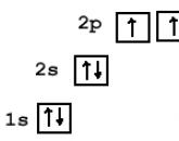 Electronic configuration of an atom
-
 How to connect electricity to the house and the plot: where to go, what you need and how much it costs How to choose a Wi-Fi adapter for a computer: external and internal
-
 How to decorate an office, study or workplace for the New Year: original ideas Decorate an office for the New Year
-
 DIY Christmas decoration
Popular
- Celebration of the day of agriculture and processing industry
- When is Agriculture Day celebrated?
- Card games at the table
- Funny and funny contests for a fun company of adults
- Polish "paratroopers" for the Soviet marines
- Project 205 missile boats
- How is life on the new Chinese destroyer
- The newest frigate "Admiral of the Fleet Kasatonov" is preparing for the first tests and going to sea Ship Admiral Kasatonov
- Submarines of the Gato type
- Insignia on the merchant fleet of the USSR Detachment of the II group