NPP control board. Automatic control and protection of NPP thermal power plants - functions and subsystems of automated control systems
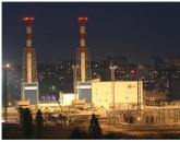
Kola NPP is the northernmost NPP in Europe and the first Nuclear Power Plant in the USSR built beyond the Arctic Circle. Despite the harsh climate of the region and the long polar night, the water near the station never freezes. The nuclear power plant does not affect the state of the environment, which is evidenced by the fact that a fish farm is located in the area of the outlet canal, where trout is bred all year round.
1.
The history of the Kola NPP began in the mid-1960s: the inhabitants of the union continued to actively develop the northern part of the territories, and the rapid development of industry required large energy costs. The country's leadership decided to build a nuclear power plant in the Arctic, and in 1969 the builders laid the first cubic meter of concrete.
In 1973, the first power unit of the Kola Nuclear Power Plant was launched, and in 1984 the fourth power unit was put into operation.

2. The station is located beyond the Arctic Circle on the shore of Lake Imandra, twelve kilometers from the city of Polyarnye Zori, Murmansk region.
It consists of four power units of the VVER-440 type with an installed capacity of 1760 MW and provides electricity to a number of enterprises in the region.
Kola NPP generates 60% of electricity in the Murmansk region, and in its area of responsibility big cities, including Murmansk, Apatity, Monchegorsk, Olenegorsk and Kandalaksha.

3.
The protective cap of the reactor No. 1. Deep under it is the case nuclear reactor, which is a cylindrical vessel.
Hull weight - 215 tons, diameter - 3.8 m, height - 11.8 m, wall thickness is 140 mm. The thermal power of the reactor is 1375 MW.

4.
The upper block of the reactor is a design that is designed to seal its vessel, accommodate drives of control systems, protection
and sensors for in-reactor control.

5.
For 45 years of operation of the station, not a single case of exceeding natural background values has been recorded. But the "peaceful" atom remains such only
with proper supervision and correct work all systems. Fifteen control posts were installed at the station to check the radiation situation.

6. The second reactor was commissioned in 1975.

7. Carrying case for 349 KNPP fuel cartridges.

8. The mechanism for protecting the reactor and plant from internal and external factors. There are forty-seven tons under the cap of each KNPP reactor nuclear fuel, which heats the water of the primary circuit.

9. Block control panel (BSHU) - think tank NPP. Designed to monitor the performance of the power unit and control technological processes at a nuclear power plant.

10.

11. The shift in the control room of the third power unit of the Kola NPP consists of only three people.

12. From such a large number of controls, eyes run wide.

13.

14. Model of the section of the active zone of the VVER-440 reactor.

15.

16.

17. The career of a nuclear specialist requires serious technical training and is impossible without striving for professional excellence.

18. Engine room. Turbines are installed here, which are continuously supplied with steam from a steam generator, heated to 255 ° C. They drive a generator that generates electricity.

19. An electric generator inside which the rotational energy of the turbine rotor is converted into electricity.

20. The generator turbine, assembled in 1970 at the Kharkov Turbine Plant, has been in use for forty-five years. The frequency of its rotation is three thousand revolutions per minute. Eight turbines of the K-220-44 type are installed in the hall.

21. More than two thousand people work at the KNPP. For the stable operation of the station, the staff constantly monitors its technical condition.

22. The length of the machine room is 520 meters.

23. The pipeline system of the Kola NPP stretched for kilometers throughout the entire territory of the power plant.

24. With the help of transformers, the electricity generated by the generator enters the network. And the steam exhausted in the condensers of the turbines becomes water again.

25. Open switchgear. It is from here that the electricity that the station generates goes to the consumer.

26.

27. The station was built off the coast of Imandra, the largest lake in the Murmansk region and one of the largest lakes in Russia. The territory of the reservoir is 876 km², the depth is 100 m.

28. Chemical water treatment area. After processing, chemically desalted water is obtained here, which is necessary for the operation of power units.

29. Laboratory. Specialists of the chemical department of the Kola NPP make sure that the water chemistry regime at the plant meets the plant operation standards.
30.

31.

32. The Kola NPP has its own The educational center and a full-scale simulator, which are designed for training and advanced training of station personnel.

33. The students are supervised by an instructor who teaches them how to interact with the control system and what to do in case of a malfunction of the station.

34. In these containers, a non-radioactive salt melt is stored, which is final product liquid waste processing.

35. The technology for handling liquid radioactive waste from the Kola NPP is unique and has no analogues in the country. It allows to reduce the amount of radioactive waste to be disposed of by 50 times.

36. Operators of the complex for the processing of liquid radioactive waste monitor all stages of processing. The whole process is fully automated.

37. Reset cleared Wastewater into the outlet channel leading to the Imandra reservoir.

38. Waters discharged from nuclear power plants are classified as clean, do not pollute environment, but affect the thermal regime of the reservoir.
39. On average, the water temperature at the mouth of the outlet canal is five degrees higher than the water intake temperature.

40. In the area of the KNPP bypass canal, Lake Imandra does not freeze even in winter.

41. For industrial environmental supervision at the Kola NPP, an automated system for monitoring the radiation situation (ARMS) is used.

42. A mobile radiometric laboratory, which is part of the ARMS, allows you to conduct gamma-ray surveys of the area along designated routes, perform air and water sampling using samplers, determine the content of radionuclides in samples and transmit the information received to the ARMS information and analysis center via radio channel.

43. The collection of atmospheric precipitation, sampling of soil, snow cover and grass is carried out at 15 permanent observation points.

44. The Kola NPP also has other projects. For example, a fish complex in the area of the discharge channel of a nuclear power plant.

45. The farm grows rainbow trout and Lena sturgeons.


47. Polyarnye Zori is a city of power engineers, builders, teachers and doctors. Founded in 1967 during the construction of the Kola NPP, it is located on the banks of the Niva River and Lake Pin Lake, 224 km from Murmansk. As of 2018, about 17,000 people live in the city.

48. Polyarnye Zori is one of the northernmost cities in Russia, and winter here lasts 5-7 months a year.

49. Holy Trinity Church on the street. Lomonosov.

50. On the territory of the city of Polyarnye Zori there are 6 children's preschool institutions and 3 schools.

51. The system of lakes Iokostrovskaya Imandra and Babinskaya Imandra flows into the White Sea through the Niva River.

52. The White Sea is an inland shelf sea of the Arctic Ocean, in the European Arctic between the Kola Peninsula Svyatoy Nos and the Kanin Peninsula. The water area is 90.8 thousand km², depths are up to 340 m.

Let us consider in more detail the block control panel of the power unit - the main switchboard from which the power unit is controlled.
The structure of the control room has undergone noticeable changes during the development of nuclear power. So far it looks like this.
The equipment of the main control room consists of one or more information panels, a control panel and workplaces or operator consoles. The panels display information of general use: block mnemonic diagram, technological parameters, signaling. Part of the information and the main controls are located on the control panel.
The control room room is usually divided into two zones (two circuits): operational zone, which houses information tools and equipment for controlling the main equipment in normal and emergency operation modes, as well as equipment for monitoring security systems, and non-operational zone, in which all controls and means of providing information are concentrated, allowing non-operational personnel, who are not process operators, to carry out all the necessary actions for the maintenance of software and hardware of the automated control system, without interfering with the process operator to manage the unit. In new projects, it is planned to create a third zone - a supervisory circuit, which allows providing non-operational, "supporting" personnel with information about the operation of the unit and the structure of technical control objects, without interfering with the main operators. An earlier version of the general view and plan of the control room is shown in fig. 12, perspective in fig. 13.
Below are the general structures of panels and control posts for a power unit with a VVER-1000 reactor.
Rice. 12. General form block control panel and layout of technical facilities:
1-8 - control and control panels of the reactor compartment, 9-16 - control and control panels of the turbine compartment, 17 - panel for collective use, 18-19 - monitors for monitoring and control of safety, 20 - keyboard, 21 - AWP SIUR, 22 - controls remote individual control, 23 - security panels, 24 - control monitors, 25 - workstation of the deputy head of the station shift, 26 - workstation of the SIUT, 27 - workstation of a crisis specialist.
|
Block control panel |
|||
|
Operational control loops |
|||
|
Security control |
General assessment of the situation | ||
|
ARM-O SIUR, SIUT |
|||
|
Non-real-time control loops |
|||
|
Operator interface zones |
|||
|
emergency management |
General assessment of the situation |
Detailed assessment of the situation and implementation of solutions |
|
|
Security panels |
mnemonic |
Shared scoreboard |
Workstation of ZNSS and security specialist, control and management panels according to aggregate-technological characteristics |
The structure of the operational control loops of the control room is as follows.
automated workplace The SIUR is located in front of the control and management panels serving the subsystems of the FMIS, CPS and mnemonic diagrams with the most important thermal measurements. CPS remote controls, four color monitors and one safety monitor, buttons for acknowledging the signaling of the mnemonic diagram and a collective use board, emergency communication equipment are located directly on the workstation.
ARM SIUT has keyboards for control and remote selective control, four color monitors and one security monitor, buttons for acknowledging the signaling of the mnemonic diagram and a panel for collective use, emergency communication equipment.
AWS ZNSS is equipped with information displays and a security display, information output keyboards.
Last time we visited the engine room of the Novovoronezh NPP. Passing between the complex interweaving of pipes, one involuntarily marvels at the complexity of this huge mechanical organism of a nuclear power plant. But what lies behind this multi-colored hodgepodge of mechanisms? And how is the station managed?
1. This question will be answered in the next room. 
2. Patiently waiting for the whole group, we find ourselves in a real MCC! Main control point or Block control panel (BCR). The brain of the 5th power unit of the Novovoronezh NPP. It is here that all the information about each element of the large organism of the station flows. 
3. The open space in front of the operators' workplaces is reserved specifically for such introductory meetings. Without interfering with the work of the staff, we can safely inspect the entire hall. Control panels diverge from the central panel with wings. One half is responsible for managing the work nuclear reactor, the second for the operation of the turbines. 
4. Looking at the control panel, it finally comes to the consciousness of what kind of monster a person has tamed and is holding tightly in his hands! The incredible number of buttons and lights, densely covering the block shield, fascinates. There are no superfluous details here - everything is consistently subordinated to the logical construction of the nuclear power plant operation process. Monitors of constantly buzzing computers stand in orderly rows. Eyes run up from the saturation and fullness of the incoming information, understandable and meaningful only for highly qualified professionals - only such people get into the chairs of leading engineers. 
5. Although the control is fully automated, and the operators carry out mainly visual control, in an emergency situation, it is the person who makes this or that decision. Needless to say, what a huge responsibility lies on their shoulders. 
6. A weighty magazine and a lot of phones. Everyone wants to sit in this place - in the chair of the shift supervisor of the 5th power unit. Bloggers could not resist, with the permission of the station workers, to try on the responsibility entailed by the possession of this position. 
7.
8. In each direction of the “wings” of the control unit hall, long rooms extend, in which relay protection cabinets stand in orderly rows. Being, as it were, a logical continuation of the panels, they are responsible for the reactor and turbines. 
9. This is such a perfectionist's dream behind a glass cabinet door. 
11. This time we are led by secret paths to the reserve shield. 
12. A reduced copy of the main control panel, it performs the same basic functions. 
13. Of course, there is no full functionality here, it is designed, for example, to safely shut down all systems in the event of a failure of the main control unit. 
14. ... And has never been used in its existence. 
15. Since our blog tour is on Novovoronezh NPP was made with an emphasis on safety, it was impossible not to talk about the most interesting simulator. A full-fledged toy and an exact copy of the block control panel. 
16. A long way to the position of a leading engineer-operator in the control room is not possible without a full-fledged training in a training center (UTP). During the training and examination process, various possible emergencies at nuclear power plants, and the adept must choose a competent and safe solution in the shortest possible time
.

17. A detailed story about the work of the USP gradually came down to a topic of particular interest to all bloggers. Big Red Button, which we noticed back in the main control unit. The emergency protection button (AZ) - sealed with a red paper tape, looked intimidating. 
18. Here, with bated breath, we were allowed to press it! Sirens howled, lights flickered across the panels. This triggered an emergency protection, which gradually leads to a safe shutdown of the reactor. 
19. Unlike the control room on the simulator, you can come up and take a closer look at everything. By the way, the control unit of the 5th power unit is unique, like any nuclear power plant. That is, an operator trained on this simulator can only work on this unit! 
20. And learning never stops. Each operator is required to undergo scheduled training for 90 hours a year. 
21. Constantly returning in our conversations with engineers to accidents at different nuclear power plants, we are trying to understand what were their causes and the existing possibilities for their occurrence. After all, it is here that scenarios of limiting or transcendental accidents are scrolled. 
22. ... The siren wailing and power outage makes us stop talking. And pay attention to the control panels, dotted with twinkling lights. Beautiful ... Well, how beautiful? It’s scary, of course, if it wasn’t on our simulator. It was this error that the control unit at Fukushima issued during the accident in 2011. 
23. In order to prevent such accidents from happening again, specialists are constantly working the highest level. There are continuous checks. Now the atom and the world are inseparable from each other. And someday the time will come for thermonuclear energy. 
The operator does not interact directly with the control object, but with its information model, displayed as a set of instruments, mnemonic diagrams, scoreboards and other means of displaying information. How and in what form this information will be presented to operational personnel, how it is placed, how convenient it is to use and how reliable, ultimately depends on the correctness of the operator's actions. To solve this problem, control panels for technological equipment and technological processes are being created.
At a nuclear power plant, consisting of several power units, there are from 9 to 13 main control panels and a significant number of local control panels. Here are considered the main, most significant shields.
Central control panel (TSChU). This board belongs to the NPP automated process control system, from which the overall coordination of the operation of power units, plant-wide systems is carried out. The central control room distributes the load between power units, controls electrical devices, and monitors the radiation safety of nuclear power plants. The shield is located in the administrative building. This is the place of residence of the NPP shift supervisor. He has an information board that creates a comprehensive picture of all events taking place at the station.
Block control panel (BCR) . This shield is the main place from which the power unit is controlled in all design modes, including emergency. Designed to monitor the operation of the reactor and turbine plant and the main equipment, control the main technological processes in normal and emergency operating conditions. It is the central post of operator activity. Through this shield, the connection between man and machine is carried out. For this reason, it is to this shield that further attention will be paid. The shield is located in the reactor room building on the side of the engine room at elevation + 6.6 m (for the VVER reactor). It is constantly attended by the shift supervisor of the power unit, senior (leading) reactor control and turbine control engineers.
Reserve control panel (RCC). With the help of this shield, the power unit is shut down and transferred to a safe cooled state, as well as long-term heat removal from the core, when this cannot be done with the control room, for example, due to fire, explosion and even death of personnel, etc. The shield is located separately from the control room, but in the zone of the reactor compartment at the level of 4.2 m (for the VVER reactor), so that the same reason does not disable both of these shields. The shield is not designed to control normal operation systems that are not related to ensuring nuclear and radiation safety. The means of displaying information and controls on the panels and consoles of the control room must correspond to their location on the control room. The permanent presence of personnel is not provided.
Local control panel (LSC). Designed to control some technological installations and plant-wide systems, as well as during commissioning or maintenance work. Their number reaches eight or more. These include the local control room for CPS, RC, chemical control (CC), ventilation system (VS), etc. The permanent presence of personnel is not provided for them.
Shield of general station devices (SHOU). Designed to control general station installations - a special water treatment system, ventilation systems, etc.
Dosimetric Control Board (ShDK) or radiation control shield. It collects information on the radiation situation at each power unit and nuclear power plant as a whole, as well as in a special building. Located in the transition from clean to dirty area.
In addition to these boards, nuclear power plants have boards for CPS, secondary instrumentation, power supply, switchgear, etc.
Page 3 of 61
The APCS function is a set of system actions aimed at achieving a particular control goal. The functions of the automated process control system are divided into information, control and auxiliary.
The content of the information functions of the automated process control system is the collection, processing and presentation of information about the state of the TOU to operational personnel, as well as its registration and transfer to other automated control systems
Consider the information functions of the APCS.
- Control and measurement technological parameters, which consist in converting the values of object parameters (pressures, flow rates, temperatures, neutron fluxes, etc.) into signals suitable for perception by operational personnel or for their subsequent automated processing. A distinction is made between the individual control function, when secondary indicating instruments operate directly from the primary converter or (with switching from a group of primary converters), and the centralized control function carried out using a computer.
- The calculation of indirect quantities is carried out with the help of a computer and provides the determination of parameter values, the direct measurement of which is either difficult for design reasons (fuel cladding temperature) or impossible due to the lack of appropriate primary converters (reactor thermal power, technical and economic indicators).
- Registration of values is carried out for the subsequent analysis of the work of the ATC. Registration is carried out on paper tapes of secondary recording devices (recorders), in computer memory, and also on computer output media (paper tapes of typewriters).
- Signaling the state of shut-off organs (latches) and auxiliary mechanisms (pumps) is carried out using color signals corresponding to certain states of valves and pumps. There is an individual signaling of the state in which each organ or mechanism has its own signal; group, in which the signal informs about the state of a group of organs and mechanisms; centralized, carried out by a computer and its output devices.
- Technological (preventive) signaling is carried out by giving light and sound signals and draws the attention of personnel to violations of the technological process, expressed in deviations of parameters beyond the permissible limits. There are individual signaling, in which each signaled parameter corresponds to its own signaling device, provided with an inscription indicating the nature of the violation, group, in which a light signal appears when one of a predetermined group of parameters deviates, centralized, carried out by a computer and its output devices
- Diagnostics of the state of technological equipment is used to determine the root cause of its abnormal operation, predict the likely occurrence of malfunctions, as well as the degree of their danger for the further operation of the equipment
- Preparation and transmission of information to related automated control systems and reception of information from these systems. The objectives of this exchange of information are discussed in § 1 1.
The content of the control functions of the automated process control system is the development and implementation of control actions on the TOU. Here, “development” means the determination, based on the available information, of the required values of control actions, and “implementation” means actions that ensure that the actual value of the control action corresponds to the required one. The development of control actions can be carried out both by technical means and by the operator; implementation is carried out with the obligatory use of technical means.
Consider the control functions of the APCS.
- The remote control function consists in the transfer of control actions from the operator to the electric drives * of the actuators (open-close) and auxiliary electric motors (turn on-off).
Nuclear power plants also have a small number of non-electrified shut-off and control elements, which are manually controlled on site; this is not done by the operators, but by special crawlers at the command of the operators.
- The function of automatic control is to automatically maintain the output values of the object at a given value.
- The function of automatic protection is used to save the equipment in case of emergency violations of the units. The simplest examples of such a function can be the opening of a safety valve when the pressure rises above the maximum allowable one or automatic shutdown of the reactor in case of emergency shutdown of several MCPs. An important variation of this function is the emergency transfer of the reserve (ESA), designed to automatically turn on the backup unit (for example, a pump) during an emergency shutdown working. This function includes notification of the fact of protection operation and their root cause.
- The automatic blocking function serves to prevent accidents that may occur due to incorrect control. It implements a technologically determined relationship between individual operations. An example of interlocks is the automatic prohibition of starting the pump in the absence of lubrication or cooling, as well as the automatic closing of the valves on the pressure and suction of the pump when its engine is turned off.
- The function of logical control is to develop discrete. control signals (such as "yes-no") based on the logical analysis of discrete signals describing the state of the object. Logic control is widely used in control systems for reactor regulators, turbines, etc. Strictly speaking, the functions of emergency protection and automatic blocking can also be considered logical control, but logical control usually includes operations performed according to more complex laws. The result of logical control are changes technological scheme(switching on, shutting down pipelines, pumps, heat exchangers) or switching in the circuits of automatic regulators.
- The optimization function maintains the extreme value of the accepted control criterion. Unlike the functions of automatic control, blocking, logical control, which are designed to stabilize the output parameters of an object or change them according to a previously known law, optimization consists in searching for previously unknown values of these parameters, at which the criterion will take an extreme value. The practical implementation of the results of determining the optimal parameters can be carried out by changing the setting for automatic controllers, making switches in the technological scheme, etc. Optimization is carried out for the TOU as a whole (the criterion is the minimum cost of energy on the unit) or for its individual parts (for example, increasing the net efficiency turbine plant by optimizing the performance of the condenser circulation pumps).
Fig 1 3. The structure of the automated process control system of the power unit.
1-14 - subsystems, 1 - control of especially critical parameters, 2 - technological signaling; 3 - remote control, 4 - automatic protection, 5 automatic control, 6 - FGU, 7 - CPS, 8 - ACS T, 9 - VRK, 10 - SRK U- KTO and KTsTK, 12 - MCP control system, 13 - auxiliary control subsystems technological systems, 14 - UVS; 15 - block operators, 16 - auxiliary technological systems operators, 17 - computer operators
Optimization can also concern the parameters of the automated process control system itself, an example of which is the determination of the optimal settings of the controllers according to the criterion of accuracy in maintaining the controlled values.
* Drives with other types of auxiliary energy (hydraulic, pneumatic) have not received distribution at nuclear power plants (except for the turbine speed control system and some types of high-speed reduction units).
Secondary functions.
APCS are functions that provide a solution to intra-system problems, i.e., designed to ensure the system's own functioning. These include checking the serviceability of APCS devices and the correctness of the initial information, automatic input of backup APCS devices in case of failures of the working ones, notification of personnel about failures in the APCS, etc. Due to the complexity of modern APCS, the value of auxiliary functions is very high, since without them normal operation of the systems is impossible.
For the convenience of development, design, delivery, installation and commissioning of automated process control systems, they are conditionally divided into subsystems. Each subsystem provides control of a part of the object or combines technical means performing any one certain function; in the first case, one speaks of a multifunctional subsystem, in the second, one-functional subsystems are relatively independent of each other and can be developed and manufactured various organizations with their subsequent docking directly at the facility. Consider the main subsystems of automated process control systems for power units (Fig. 1.3).
- The subsystem for monitoring critical parameters performs the function of control and measurement. It is implemented on personal means measurements and contains sensors, transducers, indicating and recording instruments. Recording devices also perform the recording function. The presence of this subsystem is associated with the need to maintain a minimum amount of control in the event of a computer failure. The information received by this subsystem can be used in other APCS subsystems.
- The technological signaling subsystem performs the functions of individual and group signaling. It contains primary transducers, devices that compare analog signals with set values, and devices for supplying sound and light signals. In some cases, this subsystem does not have its own primary converters, but uses information from the subsystem for monitoring critical parameters.
- The remote control subsystem provides remote control of regulating, locking bodies and mechanisms, performs the functions of signaling the state of controlled mechanisms, automatic locks and entering information about the state of the bodies into the computer.
- The subsystem of automatic protection performs the specified function, as well as some functions of automatic blocking. It consists of primary converters, alarm generation circuits, emergency protection executive bodies and devices for light and sound notification of the operator about the facts of protection operation and the root causes of accidents. In some cases, the initial information about the parameter values comes from other subsystems. Devices of other subsystems (for example, contactors of pump motors) can be used as executive bodies.
- The automatic control subsystem regulates the parameters using individual controllers. In addition, this subsystem provides control over the position of the regulators and remote control of them when the regulators are off. Possibilities modern means regulation allows you to transfer to this subsystem some of the functions of logical control.
In addition to the main devices, all subsystems contain connecting cables, panels on which devices are placed, power supplies, etc.
In addition to these subsystems, which are mainly designed to perform any one function for the block as a whole, there are a number of multifunctional subsystems designed to perform a set of functions to control any unit or technological system.
The units are controlled using devices that form a subsystem of functional group control (FGU). To start or stop the unit controlled by the FGU, it is enough to give one command, after which all operations occur automatically.
The multifunctional subsystems of the automated process control system of the block that control individual technological systems are usually called the "control system". This is due to the fact that such subsystems were developed and formalized before the advent of automated process control systems as independent systems. They may have their own computers, and then they are transferred to all the functions of managing the relevant technological equipment. In the absence of own computer, part of the functions is transferred to the computer of the APCS of the block (centralized control, calculation of indirect values, registration of some parameters, diagnostics of the state of technological equipment, exchange of information with the APCS of NPP, optimization). These multifunctional subsystems include:
- control system, protection, automatic control and monitoring of the reactor (CPS) for controlling the reactor power in all modes of its operation and their auxiliary equipment;
- automated system turbine control (ACS T), designed to control turbines and their auxiliary equipment;
- fuel refueling and transport management system that controls all mechanisms that move fuel from its receipt at nuclear power plants to its shipment for spent fuel reprocessing.
If this is dictated by the requirements of the technology, then other subsystems may also be included in the APCS. For example, units with fast neutron reactors have a subsystem for controlling the electric heating of circuits and a subsystem for controlling the speed of the main circulation pumps (CS MCP).
Some of the multifunctional subsystems are controlled by their own operators, working under the guidance of block operators
Modern nuclear power plants also have multifunctional subsystems that perform a full set of information functions for monitoring homogeneous mass parameters. These include:
- in-reactor control system (IRC) designed to control heat release values, temperatures and other parameters inside the reactor core;
- radiation monitoring system (RMS) designed to monitor the radiation situation of process equipment, NPP premises and the surrounding area;
- systems for monitoring the tightness of fuel claddings (CGO) and monitoring the integrity of technological channels (CCTC), monitoring the state (integrity) of fuel claddings and technological channels based on the analysis of data on the activity of the coolant and other reactor parameters.
The most important subsystem of the automated process control system, which performs the most complex information and control functions, is the control computer system (CCS) [or the control computer complex (CCC)]. In the automated process control system of the UVS units, they can perform almost all information and control functions.
NPP control panels
Control board(ShU) is a specially allocated room intended for permanent or periodic stay of operators, with panels, consoles and other equipment located in it, on which the technical means of automated process control systems are installed and with the help of which control is carried out technological process NPP control is organized from several control rooms.
The central control panel (TSChU) refers to the automated process control system for nuclear power plants. From it, the overall coordination of the operation of power units, the control of electrical switchgear and plant-wide systems is carried out. The central control room is the place of residence of the station engineer on duty (DIS) or the NPP shift supervisor. Near the central control room, a room is allocated for the location of the UVS of the automated process control system of the NPP. If necessary, to control some general station equipment - special water treatment plants, boilers, ventilation systems - a shield of general station devices (SHOU) (or several ShOU) is organized.
The main control of the technological process of the block is carried out from the block control panel (BCR). According to the nuclear safety requirements, for each NPP unit, a backup control panel (RCC) is organized, which is designed to carry out operations to shut down the unit in situations in which it is not possible to carry out these operations from the control room (for example, in the event of a fire at the control room).
To control some auxiliary systems, both station-wide and block, local control panels (LSC) are organized. Depending on the technological requirements these shields are intended for permanent or periodic stay of operational personnel (for example, during fuel refueling). Often, special rooms are not allocated for the local control room, but they are located directly at the controlled equipment (for example, the local control room of turbogenerators is located directly in the engine room).
Let us consider in more detail the organization of the control room. A modern power unit is a complex control object with a large number of measured (up to 5-10 thousand) and controlled (up to 4 thousand) quantities. Each block is controlled by two or three operators. An increase in the number of operational personnel is not possible due to the difficulty of coordinating the work of a larger number of operators. In addition, an increase in personnel reduces the efficiency of nuclear power plants. Naturally, even when modern control facilities (including computers) are used, a great mental and physical burden falls on operators.
When designing the APCS of the unit, they tend to reduce the number of controlled parameters and controlled objects. However, due to the peculiarities of the technology, as mentioned above, the number of controlled and controlled parameters is measured in thousands, and placing such a number of indicating devices and controls on the operational fields directly in front of the operators is simply impossible. . In modern automated process control systems, the following methods are used to reduce operational fields.
- location of all devices that do not require control by operators (regulators, FGU devices, relay blocking and protection circuits, etc.) on special non-operational panels taken out to separate rooms of the control room. Maintenance of these devices is carried out by personnel who ensure the serviceability of their operation, but are not directly involved in the management of the unit;
- the use of centralized control with the help of a computer and a decrease in the number of parameters controlled on individual secondary devices; in modern process control systems of blocks, the number of such parameters is no more than 10% of the total;
- the use of calling, group and functional-group controls, in which one body controls several actuators;
- removal of secondary instruments and controls, necessary only for relatively rare operations (preparation for the start-up of the unit), to auxiliary panels located in the operational room of the control room, but outside the main control loop (on the side or behind the operators). With a large number of auxiliary systems, the control of which is not directly related to the control of the main technological process, a special auxiliary systems shield (ASS) can be organized for them, located in close proximity to the operational circuit of the control room.
Another way to reduce the burden on operators is to make it easier to decode incoming information and find the right controls. For this, in particular, in modern automated process control systems, mnemonic diagrams are used. They represent a simplified image of the technological scheme of equipment with conditional images of the main units (heat exchangers, pumps). At the locations of the images of the corresponding units, as well as the shut-off organs, there are status signaling devices (light bulbs with light filters), and at the locations of the images of the regulatory bodies - position indicators. 
Fig 1.4. An example of the image of a technological line on a mnemonic diagram
1 - pump mnemonic with status indicator, 2 - valve mnemonic with status indicator, 3 - regulator position indicator; 4 - tank mnemonic, 5 - pump control key; 6 - valve control key, 7 - regulator control key, 8 - pressure deviation signaling device, 9 - level deviation signaling device, 10 - red light filter, 11 - green light filter
In some cases, the mnemonic diagram contains devices that show the values of technological parameters, as well as devices that signal a deviation of these parameters from the norm. If the mnemonic diagram is located within the reach of operators, controls are also installed on it (Fig. 1-4).
a - with a separate remote control; b - with attached remote control, 1 - vertical panels, 2 - remote control; 3 - countertop; 4 - vertical attachment, 5 - inclined panel 
Fig. 15. Options for the layout of the operational circuit of the control room (section):
Structurally, the operational circuit of the control room is usually made in the form of vertical dashboards and a separate console (Fig. 1.5, a). On the vertical panels are large-sized instruments, as well as mnemonic diagrams and rarely used controls. When the mnemonic is located at the top of the console, it is usually slanted to improve visibility. The operational part of the control panel consists of an inclined (or horizontal) tabletop, on which are located the controls, indicators of the position of shut-off and regulatory bodies and indicators of the status of auxiliary electric motors. 
Figure 1 6. Layout options for the operational circuit of the control room (plan)
a - arched, b - linear, 1 - operational panels, 2 - remote control, 3 - table-console, 4 - auxiliary panels; I - III - control zones, respectively, of the reactor, steam generators and turbogenerators
In some cases, mnemonic diagrams are located both on the tabletop and on the vertical attachment of the remote control. Consoles serviced by one operator have a significant length (up to 5 m), and during transient modes, the operator works while standing. In stationary modes, when the volume of control operations is small, the operator can work while sitting. To do this, a special workplace is allocated on the remote control, near which the most important controls and controls are located. The tabletop of this workplace should be free from instruments so that the operator can use instructions, keep records, etc. remote control, and at a special table-remote, on which only the telephone is located, and in modern systems- and communication devices with computers
Auxiliary panels (as well as LCM panels) usually do not have separate consoles, but are made in the attached version (Fig. 1.5, b), they work at such consoles, as a rule, while standing.
Basically, two options for the layout of the operational circuit of the control room are common: arc-shaped and linear (Fig. 1.6). Usually the unit is controlled by two or three operators from one, two or three consoles. For convenience of passage to the vertical panels, gaps are made between the consoles.
Operational panels are located directly in front of the consoles, auxiliary panels are located on the side and behind. Usually, in the center of the operational room of the control room, there is a table-console of the unit shift supervisor (or senior operator). At the same table, operator workplaces can be allocated for sitting.
The placement of instruments and devices on the panels and consoles of the control room follows the sequential technological principle, i.e. from left to right, in accordance with the technological process (reactor - MCP - steam generators - turbogenerators). Accordingly, the left auxiliary panels are assigned to control the reactor and steam generators, the right - turbogenerators.
In the room of the operational circuit of the control room, the specified illumination of panels and consoles (200 lux), temperature (18-25 ° C) and humidity (30-60%) of the air are provided; noise level should not exceed 60 dB. MCRs are performed according to a special architectural project, which takes into account aesthetic and engineering requirements. The approach of cable flows to all switchboard devices must be provided. The control room room must comply with safety standards, fire safety and rules for the installation of electrical installations.
The operational contour of the control room occupies only a part of all rooms of the control room. A significant area is occupied by non-operational panels. Typically, the operating circuit is located in the central part of the control room, and non-operational panels are located in the rooms on the sides of the operating room. There are layouts in which non-operational panels are placed under the operating room. Given the significant number of cable connections between the operating circuit of the control room and the computer, the computer room is also sought to be brought closer to the operating room.
The standby control panel (RCC) is located in a special room separated from the control room by a fire-resistant fence or spaced from it at some distance, but in such a way that access to it can be provided without hindrance and in a minimum time. The volume of monitoring and control equipment installed on the control room must be sufficient for normal shutdown of the unit even in the presence of accidents in technological equipment while meeting all safety requirements.


Popular
- Billionaire Carlos Slim Helu: biography, fortune Carlos Slim Helu
- Visual merchandising Design of a shoe store taking into account the age and gender of customers
- How to sell homemade cakes and make money on it?
- How to open a car service: the idea of \u200b\u200ba car business
- Production of paper cups
- New business ideas New business trends
- Small business ideas for beginners in the garage
- Women's wedding planning business - what you need to know?
- Features of entrepreneurial activity for the production and sale of maggots for fishing Equipment for breeding maggots
- Magellan - production of board games and gifts in Russia