Digital technologies: CTP and CTcP flat offset printing. Course work Development of technology for manufacturing printing plates for flat offset printing according to the scheme "computer printing plate" Technology for manufacturing printing plates for flat offset printing
Offset Printing Form Manufacturing Technologies
Yuri Samarin, Dr. tech. sciences, prof. MGUP im. Ivan Fedorov
In modern prepress processes for the production of offset printed forms three technologies are mainly used: "computer - photoform" (Computer-to-Film); Computer-to-Plate and Computer-to-Press.
The process of manufacturing offset printing plates using the "computer - photoform" technology (Fig. 1) includes the following operations:
- punching holes for pin registration on a photoform and a plate using a perforator;
- format recording of the image on a form plate by exposing the photoform on a contact-copy machine;
- processing (developing, washing, applying a protective coating, drying) of the exposed plate copies in the processor or production line for processing offset printing plates;
- quality control and technical proofreading (if necessary) of printed forms on the table or conveyor to view the forms and correct them;
- additional processing (washing, applying a protective layer, drying) forms in the processor;
- heat treatment of molds in a kiln for firing (if necessary, increase the circulation resistance).

Rice. 1. Scheme of the process of manufacturing offset forms using the “computer-photoform” technology
The quality of photoforms must meet the requirements of the technological process of manufacturing printing forms. These requirements are determined by the method of printing, the technology and materials used. For example, a set of color-separated raster transparencies for offset sheet printing on a multi-color machine (green printing) on the most common coated paper today should have the following characteristics:
- absence of scratches, creases, foreign inclusions and other mechanical damage;
- minimum optical density (optical density of the base of the film, taking into account the density of the veil) - no more than 0.1 D;
- maximum optical density for photoforms made by laser exposure (taking into account the density of the veil) - not less than 3.6 D;
- the core density of the raster dot is not less than 2.5 D;
- the minimum value of the relative area of raster elements is no more than 3%;
- the presence on the photo form of the names of paints;
- tilt angles of the raster structure correspond to the specified values for each paint;
- the lineature of the raster structure corresponds to the given one;
- misalignment of images on photoforms of one set by crosses - no more than 0.02% of the diagonal length. This value takes into account laser exposure repeatability tolerances and the amount of film distortion;
- the presence of control marks and scales on the photoform.
A photoform of a full-size printed sheet can be obtained either directly by displaying an image in a photo output device of the appropriate format, or by editing individual strips from photoforms. In this case, the assembly is carried out manually on the assembly table.
Forms of offset flat printing on whitespace and printing elements have different physical and chemical properties in relation to printing ink and wetting agent. Gap elements form hydrophilic surfaces that perceive moisture, and printing elements form hydrophobic areas that perceive printing ink. Hydrophilic and hydrophobic areas are created during the processing of the plate material.
Forms of offset flat printing can be divided into two main groups: monometallic and polymetallic - depending on what is used to create space and printing elements - one metal (monometal) or several (polymetal). Currently, polymetallic molds are practically not used. For all modern ways in the manufacture of monometallic forms, hydrophobic printing elements are created on films of the copying layer, firmly adhered to the developed surface of the metal, and blank ones are created on adsorption hydrophilic films formed on the surface of the base metal.

Rice. 2. Methods of contact copying: a - positive; b - negative. 1 - substrate; 2 - copy layer; 3 — photoform diapositive; 4 - negative photoform
Offset printing plates are made by negative or positive contact copying (Fig. 2). With the negative method, negatives are copied onto the photosensitive copy layer, and in this case the hardened copy layer serves as the basis for the printing elements. With the positive method, a photosensitive layer is copied from a transparencies, and then the exposed areas dissolve when the copy is processed.
The positive copying method ensures greater fidelity in the reproduction of image elements and the stability of the printing elements during printing.
For the manufacture of offset forms, centrally produced pre-felt offset positive or negative plates are used.
The pre-sensed positive printing plates are a multilayer structure (Fig. 3). They are produced on the basis of ultra-clean rolled aluminum and are the result of a complex and lengthy process that guarantees a high quality product. These plates are designed for the production of high quality offset plates for sheetfed and web presses using positive copying.

Rice. 3. The structure of the positive offset plate: 1 - aluminum base; 2 - electrochemical graining; 3 - oxide film; 4 - hydrophilic sublayer; 5 - photosensitive copy layer; 6 - micropigmented layer
After electrochemical treatment, oxidation and anodization, the aluminum base acquires physical and chemical characteristics that provide high resolution and runtime, stability of the hydrophilic properties of blank elements on an offset printing plate, uniform distribution of the ink layer and moisturizing solution over the entire plate area.
After exposure is provided good performance color of the copy layer, which allows you to control the quality of the copy before development. The printing elements formed by the copy layer have a good contrast compared to blank areas, which allows the plates to be used for scanning in automatic control and offset printing control systems. In the process of printing, due to the developed capillary structure of the anodized layer, an optimal ink-water balance is quickly established, which is stably maintained during the printing process. The copy printing layer is characterized by high resistance to the action of alcoholic moisturizing solutions and cleaning materials. The oxide layer strengthens the gaps and increases the runtime of printing plates, protecting their surfaces from scratches and abrasion. The high-quality aluminum base provides a snug fit to the forme cylinder and a break-resistant form.
High light sensitivity and photo-latitude of the copy layer allow to reduce the exposure time, ensure accurate reproduction and simplify the development process.
Micropigmentation (vacuum coating) of the copy layer contributes to close contact with the photoform during exposure and the rapid creation of a vacuum.
Main technical indicators positive (analogue) printing plates have approximately the following values:
- roughness - 0.4-0.8 microns;
- anodized layer thickness - 0.8-1.7 microns;
- thickness of the copy layer - 1.9-2.3 microns;
- spectral sensitivity - 320-450 nm;
- energy sensitivity - 180-240 mJ / cm2;
- exposure time (at illumination of 10,000 lux) - 2-3 minutes;
- minimum size reproducible strokes - 6-8 microns;
- lineature bitmap- 60 lines / cm (150 lpi);
- gradation transmission of raster elements - in the highlights 1-2%, in the shadows 98-99%;
- runtime - up to 150 thousand prints without heat treatment and up to 1 million prints with heat treatment;
- color of the copy layer - blue, green, dark blue;
- plate thickness - 0.15; 0.2; 0.3; 0.4 mm.
Printing forms should have pin holes of various configurations (round, oval, rectangular) on the leading edge. Pin (registration) holes facilitate the alignment of images obtained when printing from ready-made printing forms.
Photoforms and plate plates before copying with registration holes are put on the pins of a special ruler supplied with the puncher. The configuration, the number of holes and the distance between them (Fig. 4) depend on the print format and the accepted register standard, which must correspond to the pin ruler of the printing press. The finished form is worn in printing machine on the corresponding pins.

Rice. 4. Printing plate with pin holes: L - image field format; S is the leading edge of the mold; D - distance between grooves
For punching pin holes in photoforms and form plates, special devices are used - punchers with a manual or pedal drive.
Before exposure, it is necessary to carefully prepare the glass of the copy frame - clean it from dirt and dust using special tools.
The plate is placed in a copy frame and a mounting of photoforms is placed on it with an emulsion layer to the copy layer of the plate. The combination of the plate and mounting is carried out using pins located on a special ruler. The image on the plate must be readable.
In the absence of a pin register system, the copier measures the specified valve size with a ruler on both sides (the distance from the mounting cut marks to the edge of the plate) and fixes the mounting with adhesive tape.
Behind the cut field of the image, the scales for controlling the copying process SPSh-K, RSH-F or the control scale Ugra-82 are installed.
For exposure, it is necessary to ensure full contact between the mounting of transparencies and the surface of the plate, which is achieved due to a two-stage set of vacuum in the contact copy machine.
The exposure mode depends on the type of plate, the power of the illuminator (the illumination of the glass of the copy frame must be at least 10 thousand lux), the distance from the illuminator to the glass of the copy frame, the nature of the transparencies and is determined empirically.
The correctness of the choice of exposure time is evaluated by reproducing the sensitometric scale on the copy after it has been developed on the form: for test printing, 3-4 fields of the SPSh-K scale (optical density 0.45-0.6) must be fully developed, for production printing - 4- 5 fields (optical density 0.6-0.75).
In order to reduce the volume of proofreading to eliminate a foreign image (strokes from the edges of the film on the installation, traces of adhesive tape), additional exposure is carried out with a scattering (matted) film. The exposure time with diffuser film is usually 1/3 of the main exposure time.
At the same time, it should be borne in mind that the use of a scattering film does not affect the reproduction of small raster dots and line elements if they have a high optical density and contrast. For highly artistic publications, in order to avoid the defect of non-copying, the use of a scattering film during exposure should be excluded.
For development, the exposed plate is placed on the processor loading table and fed onto the transport rollers. Further advancement of the plate occurs automatically.
Depending on the type of processor, the development is carried out by jets of solution supplied to the copy from the tank of the developing section, or by immersing the copy in a cuvette with a developing solution with simultaneous mechanical action of the fluffy roller.
An offset copy is developed in accordance with the capabilities of the processor at a temperature of 21-25 ° C for 20-35 seconds. For each type of plate, their manufacturers give recommendations on the composition and consumption of the developer, which must be followed.
For manual development, the same developing solutions are used. The process is carried out at a temperature of 21-27 °C. With a small amount of image on the form, the development time is 45-60 s. With an average and large number of printing elements, it is recommended to first develop the plate for 30-40 seconds, check and, if necessary, continue developing for another 30-40 seconds. It is recommended to develop the copy using a soft swab. At the same time, abrasive particles of sediment and undiluted developer concentrate should not get on the surface of the plate.
The speed of the offset copy depends on the type of processor, the operating time of the developer and its temperature.
The temperature of the solution in the section is set on the mode setting panel in accordance with technical parameters processor. It is necessary to strictly observe the temperature regime of the developing solution. At temperatures below the recommended, it is possible that the copy layer is not completely removed from the blank areas, which, when printed, will lead to the effect of “shadowing” the form. Higher temperatures than recommended make the developer more aggressive, which can damage the print elements and reduce the runtime of the printing plates.
The developing solution, as it is depleted, must be corrected with fresh portions, followed by a complete replacement. Modern processors provide a system for constant replenishment of the developer. For this, a container with regenerate is provided, from where fresh portions of the developer-regenerate are fed into the development section after passing through each form.
Washing is carried out in a jet way automatically in the washing section. Excess water on the form is squeezed out by rollers at the outlet of the section.
The application of a protective coating (gumming) on the form is carried out automatically by the roller method, followed by pressing at the exit from the section. Coating rollers must be thoroughly rinsed with water before use.
Drying is carried out by blowing the form with the help of fans with air heated to 40-60 ° C when passing through the drying section. For quality control, the finished form is transferred to the table for proofreading and carefully reviewed. Whitespace elements of the form must be fully developed. All defects of white space elements: traces of adhesive material, shadow from the edges of the transparencies, excessive marks and crosses, etc. - removed with a minus correction pencil or a thin brush dipped in proofreading gel. Correction is carried out on a protective coating. In the corrective composition, the copy layer is completely dissolved, so it should be applied very carefully, without affecting the image. The duration of the proofreading until the visual dissolution of the layer is 5-10 s.
Defects in the printing elements: gaps on the plates, the absence of part of the picture, etc. - correct with a "plus" correction pencil: a thin layer of varnish is applied to the missing elements and local heating is carried out to fix it.
The corrected form is subjected to additional processing, for which it is introduced into the washing section of the processor, then the protective coating is again applied and dried. The form is ready!
Heat treatment is carried out in special installations - kilns for firing, consisting of a loading table, a heating cabinet and an unloading table.
Forms intended for heat treatment are necessarily covered with a layer of colloid in order to protect blank elements from dehydration, and printing elements from cracking.
The protective coating is applied to clean forms, having previously removed the gumming layer from them, manually on the table or in the processor. In the latter case, the colloid is poured into the protective coating section. The mold is placed on the loading table and fed onto the transport rollers. Further promotion is carried out automatically.
The temperature and time of heat treatment are set on the control panel for setting the modes: temperature 180-240 ° C, time 3-5 minutes. After heat treatment, a visual control of the shape is carried out: the image becomes dark, saturated and has the same color throughout the format. A layer of colloid can serve as a protective coating during storage of molds for no more than a day. For long-term storage of forms, it is removed from the surface with warm water using a sponge and a conventional protective coating is applied.
Forms are shifted with sheets of clean paper and stored in a horizontal position on racks in a room with non-active lighting, away from heating appliances.

Rice. 5. Scheme of the process of manufacturing offset forms using the "computer-printing form" technology
The process of manufacturing offset printing plates using the "computer-printing plate" technology (Fig. 5) includes the following operations:
- transfer of a digital file containing data on color separation images of a full-size printed sheet to a raster processor (RIP);
- automatic loading of the form plate into the forming device;
- digital file processing in RIP (data reception, interpretation, image rasterization with given lineature and raster type);
- element-by-element recording of color-separated images of full-size printed sheets on a form plate by exposing it in a form output device;
- plate copy processing (developing, washing, applying a protective layer, drying, including, if necessary, for some types of plates, preheating of the copy) in an offset plate processor;
- quality control and technical proofreading (if necessary) of printed forms on a table or conveyor for viewing forms;
- additional processing (washing, applying a protective layer, drying) of the corrected printing plates in the processor;
- heat treatment (if it is necessary to increase the circulation resistance) of molds in a kiln for firing;
- punching pin (registration) holes with a puncher (in the absence of a built-in puncher in the forming device).
For the manufacture of offset printing plates using the "computer-printing plate" technology, light-sensitive (photopolymer and silver-containing) and heat-sensitive plate plates (digital) are used, including those that do not require chemical treatment after exposure.
Plates based on a photopolymer layer are sensitive to radiation in the visible part of the spectrum. Plates for green (532 nm) and violet (410 nm) lasers are currently common. The structure of the plates is as follows (Fig. 6): a monomer layer is deposited on a standard anodized and grained aluminum base, protected from oxidation and polymerization by a special film, which dissolves with water during further processing. Under the influence of light of a given wavelength, polymerization centers are formed in the monomer layer, then the plate is subjected to heating, during which the polymerization process is accelerated. The resulting latent image is etched with a developer, while the unpolymerized monomer is washed out, and the polymerized printing elements remain on the plate. Photopolymer offset plates are designed for exposure in shapers with a visible laser - green or violet.

Thanks to high speed Exposure and ease of processing, these plates are widely used and provide the ability to obtain 2-98% raster dot with lineature up to 200 lpi. If they are not subjected to additional heat treatment, the plates withstand up to 150-300 thousand prints. After firing - more than a million prints. The energy sensitivity of photopolymer plates ranges from 30 to 100 μJ/cm2. All operations with plates must be carried out under yellow light.
Plates based on a silver-containing emulsion are also sensitive to radiation in the visible part of the spectrum. There are plates for red (650 nm), green (532 nm) and violet (410 nm) lasers. The principle of the formation of printing elements is similar to the photographic one - the difference lies in the fact that in the photograph the silver crystals that were hit by light remain in the emulsion, and the rest of the silver is washed out with the fixer, while on the plates the silver from the unexposed areas passes to the aluminum substrate and becomes the printing elements , and the emulsion, together with the silver remaining in it, is completely washed off.
In recent years, plates light-sensitive to the violet region of the radiation spectrum (400-430 nm) have been increasingly used. For this reason, many shapers are equipped with a violet laser. During the exposure of these plates (Fig. 7), the violet laser beam activates the silver-containing particles on the gap elements. Unexposed areas after processing with a developer form printing elements.

In the development process, silver-containing particles are activated, while they form stable bonds with gelatin. Particles that have not been illuminated remain mobile and capable of diffusion.
At the next stage, silver ions that have not been exposed to illumination diffuse from the emulsion layer through the barrier layer to the surface of the aluminum base, forming printing elements on it.
Once the image is fully formed, the gelatin fraction of the emulsion and the water-soluble barrier layer are completely removed during washout, leaving only deposited silver print elements on the aluminum base.
These plates provide a 2-98% dot at 250 lpi, their print run is 200-350 thousand prints, and the photosensitivity is maximum. The energy sensitivity of the plates is in the range from 1.4 to 3 μJ/cm.
Due to the high sensitivity, the plate requires less time and energy to expose. This, in turn, leads to both increased productivity of the output device, and to reduce the power consumption of the laser and to extend its service life. As a result of using a thin silver layer, which is more than an order of magnitude thinner than the polymer layer, the dot gain of the ink is reduced, which leads to an increase in the quality of the print. All operations with plates must be carried out under yellow light. Plates based on a silver-containing emulsion are not recommended for printing with UV inks, as well as for firing.
The heat-sensitive plates have the following structure: a layer is applied on the aluminum base polymer material(thermopolymer). Under the influence of IR radiation, the coating is destroyed or changes its physicochemical characteristics, as a result, during subsequent chemical processing, blank (in the case of a positive material) or printing (in a negative process) elements are formed. To expose such plates, a laser with a wavelength of 830 or 1064 nm is used.

Rice. Fig. 8. Technological process of recording and processing of thermoplates: 1 - emulsion layer (thermopolymer); 2 - aluminum substrate; 3 - laser beam; 4 - exposed thermopolymer; 5 - heating element; 6 - printing elements of the form; 7 - developing solution; 8 - printing ink
The resolution of the thermosensitive plates can provide image recording with a lineature of up to 330 lpi, which corresponds to obtaining a one percent dot with a size of 4.8 microns. At the same time, the print run of the obtained printing plates reaches 250 thousand prints without firing and 1 million prints with firing. The processing of these plates after exposure consists of three steps (Fig. 8):
- preliminary firing - the surface of the mold is fired for approximately 30 seconds at a temperature of 130-145 ° C. This process strengthens the printables (so they can't dissolve in the developer) and softens whitespace. Pre-firing is a mandatory operation;
- developing - a standard positive developing process: immersion in a solution, brushing, washing, gumming and forced air drying;
- firing - after processing, the plate is fired for 2.5 minutes at a temperature of 200 to 220 ° C to ensure its strength and greater circulation resistance.
Currently on Russian market a wide range of heat-sensitive plates is presented, including new generation plates that do not require preheating for processing. For the most part, these plates provide 1-99% dots with a screen lineature of 200 lpi, a print run of 150,000 prints without firing, and their photosensitivity varies, being in the range from 110 to 200 mJ/cm2.
For chemical treatment of exposed plates, it is recommended to use reagents from the same manufacturer intended for this type of material. This ensures that high specifications, potentially embedded in modern uniform material.
Form plates that do not require chemical treatment after exposure are called processless. Currently, two types of shaped materials have been developed that do not require chemical treatment: with thermally removable layers (thermoablative) and with layers that change the phase state.
Thermal ablation plates are multilayer, and the gap elements in them are formed on the surface of a special hydrophilic or oleophobic layer. In the process of exposure, selective thermal removal of a special layer by IR radiation (830 nm) takes place. There are positive and negative versions of thermoablative plates. In negative plates, the oleophobic layer is located above the oleophilic printing layer, and during the exposure process, it is ablated from future printing elements of the form. In positive plates, the opposite is true: above is the oleophilic printing layer, which is removed during exposure from future blank elements of the form. The products of combustion are removed by an exhaust system, which must be equipped with a molding device, and after exposure, the plate is washed with water.
Thermoablative mold materials are based on aluminum plates or polyester films.
The disadvantages of processless plates include more high price and low circulation resistance (about 100 thousand prints).
In operational printing, in the production of small-circulation products that do not require high quality (instructions, letterheads, etc.), offset printing forms on paper and polymer bases are used.
Paper-based offset printing forms can withstand print runs of up to 5,000 copies, however, due to the plastic deformation of the moistened paper base in the zone of contact between the plate and offset cylinders, the line elements and raster dots of the plot are distorted, so paper forms can only be used for single-color printing.
The production technology of paper offset forms is based on the principles of electrophotography, which consist in the use of a photo-semiconductive surface to form a latent electrostatic image, which is subsequently developed.
A special paper substrate coated with a photoconductive coating (zinc oxide) is used as a form material. Form material, depending on the type of processing device, can be sheet and roll.
The advantages of this technology are the speed of making a printing plate (less than a minute), ease of use and low consumable cost. Such printing forms can be obtained by direct recording of text and image information in a conventional laser electrophotographic printer. In this case, no additional form processing is required.
Polymer-based forms, such as polyester, have a maximum runtime of up to 20,000 prints good quality with a lineature up to 175 lpi and a gradation range of 3-97%.
The basis of the technology is a polyester roll photosensitive material, which works on the principle of internal diffusion transfer of silver. During exposure, the silver halide is exposed. During chemical treatment, diffusion transfer of silver from unexposed areas to the upper layer, which is susceptible to paint, is carried out. This workflow requires negative exposure. Exposure of polyester materials can be carried out on some types of photo output devices.

Rice. 9. Scheme of the process of obtaining offset printing forms using the “computer-printing machine” technology
The process of obtaining offset printing forms using the “computer-printing machine” technology includes the following operations (Fig. 9):
- transferring a digital file containing data on color separation images of a full-size printed sheet to a raster image processor (RIP);
- digital file processing in RIP (reception, interpretation of data, rasterization of the image with a given lineature and raster type);
- element-by-element recording on a plate material placed on a plate cylinder of a digital printing machine, images of a full-size printed sheet;
- print run prints.
One such technology implemented in non-damp digital offset presses is thin coating processing. These machines use a roll-form material, on a polyester basis of which heat-absorbing and silicone layers are applied. The surface of the silicone layer repels ink and forms blank elements, and the thermally absorbing layer removed by laser radiation forms printing elements.
Another technology for obtaining offset printing forms directly in a digital printing machine is the transfer of thermopolymer material on the transfer tape to the surface of the form under the action of infrared laser radiation.
The production of offset printing plates directly on the plate cylinder of the printing machine reduces the duration of the plate process and improves the quality of printing plates by reducing the number of technological operations.
Ministry of Education Russian Federation
Faculty: Printing technique and technology
Form of study: part-time
course project
Discipline: Technology of Form Processes
Topic: Development of technology for manufacturing printing plates for flat offset printing according to the "computer - printing plate" scheme
Student: Chernysheva E.A.
Group VTpp-4-1
Supervisor spruce: Nadirova E.B.
Moscow
2011
MOSCOW STATE UNIVERSITY OF PRINTING named after I. Fedorov
Faculty of Printing Engineering and Technology
Specialty: Technology of printing production
Form of study: part-time
Department: Technology of prepress processes
EXERCISE
for a course project
Student (s) ______________________________ of the course _______________________ group
(FULL NAME.) ______________________________ ______________________________ _________
1. Discipline ______________________________ ______________________________ ____
2. Theme of the project ______________________________ ______________________________ ___
3. Project defense period ______________________ ______________________________ ____
4. Initial data for the project ___________________ ______________________________
5. Content of the project ______________________ ______________________________ _____
______________________________ ______________________________ _________________
6. Literature and other documents recommended to the student for study: ____________
______________________________ ______________________________ _________________
6.1. Numbers of sources according to guidelines ____ ___________________________
6.2. Additional sources ______________________________ ___________________
7. Date of assignment issue
"___" __________ 2011
Project Manager ______________________________ ________________________
(academic title, degree, full name, signature)
The task was accepted for execution by ______________________________ ___________________
(signature, date)
Content
Abstract 4
Introduction 5
1. Technical characteristics and design indicators of edition 6
2. General technological scheme for manufacturing a product 7
3. Technology of the mold process, general scheme 9
4. Equipment, materials, software 12
5. Quality control of finished products 13
6. Process flow chart 16
7. Imposition 17
8. Profitability, scope of work and labor intensity 18
Conclusion 19
List of used literature 21
Essay
Goal of the work: Development of technology for manufacturing printing plates for flat offset printing according to the "computer - printing plate" scheme.
Legend:
TOII is a technology for processing visual information.
LTTE is a text information processing technology.
LEU - laser exposure device.
The content of the work: 19 pages, 2 diagrams, 2 drawings.
Introduction
Form processes are a complex of technological operations based on the use of analog and digital technologies for the manufacture of printing plates, which are material carriers. graphic information intended for printing reproduction.
When developing this course project, such goals were pursued as: consolidating and expanding knowledge within the discipline, acquiring skills in the process of working with scientific and technical literature and electronic sources of information, developing skills in using reference and regulatory technical documentation on printing equipment and technology, and also on publishing processes, obtaining initial skills in designing and calculating the form process.
Despite the variety of ways to obtain printed products, the method of flat offset printing occupies a leading position. This is due to the ability to reproduce single- and multi-color images of any complexity with high graphic, gradation and color accuracy using raster structures with lineature up to 120 lines/cm. This method allows you to print publications on paper of various weights using a wide variety of methods for making printing plates. The method is also characterized by a high degree of automation of plate and printing processes, good economic performance, high-performance printing equipment.
1. Technical characteristics and design indicators of the publication
| Name of indicator and characteristics | Indicator value | |
| in the edition taken as a sample | in the edition accepted for development | |
| 1 | 2 | 3 |
| Publication type: - on purpose - by sign nature of information - by frequency |
tutorial text-pictorial non-periodic |
tutorial text-pictorial non-periodic |
| Publication format: - declared format - product of width and height - share of paper sheet |
80x98 195х255 16 |
80x98 195х255 16 |
| Volume of publication: - in physical printed sheets - in paper sheets - in pages |
19 9,5 304 |
19 9,5 304 |
| Edition circulation (thousand copies) | 2500 | 2500 |
| Printing design - brilliance of the publication and its constituent elements - nature of inline images, screening lineature - area of illustrations in stripes and as a percentage of the entire volume - the total amount of text in the bands - printing method - type of printing used and type of printing inks |
raster 60 lines/cm 60% 183 121 offset book block: offset cover: coated |
4+4 (book block) 4+0 (cover) raster 60 lines/cm 60% 183 121 offset book block: offset cover: coated paint: for offset sheet printing |
| Edition design - number of notebooks - number of pages in one notebook - the number and nature of additional elements - how to fold notebooks - block assembly method - type and design of the cover, design |
19 16 cover 3-fold compilation |
19 16 cover 3-fold compilation type 3, paper 175 g/m2 coated, 4+0, spine straight |
2. General technological scheme for the manufacture of the product
In the method of flat offset printing, printing forms are used, on which the printing and blanking elements are located almost in the same plane. They have selective properties for the perception of oil-containing paint and a moisturizing solution - water or an aqueous solution of weak acids and alcohols. The printing elements of the form are hydrophobic, the blanks are hydrophilic.
Fig.1. Form of flat offset printing: 1 - printing elements, 2 - blank elements
The main difference between this printing method and letterpress and gravure printing is the use of an intermediate surface (offset cylinder) when transferring ink from the printing plate to the printed material.
Flat offset printing forms differ from letterpress and gravure printing forms in two main ways:
- by the absence of a geometric significant difference in height between the printing and blank elements (CS thickness: 2–4 microns);
- by the presence of a fundamental difference in the physical and chemical properties of the surface of the printing and blanking elements.
To obtain these forms, it is necessary to create stable hydrophobic printing and hydrophilic blank elements on the surface of the form material.
Methods for obtaining printed forms are format and element-by-element notation.
format notation- this is the recording of an image over the entire area at the same time (photographing, copying). Element notation– the image area is divided into some discrete elements, which are recorded gradually element by element (recording using laser radiation).
original - a text or graphic work that has undergone editorial and publishing processing and prepared for the production of a printed form. Originals are classified into the following types.
Analog original- the original on a physical medium, which requires translation into a digital file for its subsequent processing and reproduction.
Digital original– the original, the informative part of which is contained in an encoded form.
Image scanning, computer processing and screen proofing are covered in detail in the ITII discipline.
Text file production, proofreading and computer layout of strips are studied in the discipline of LTTE.
Electronic editing with imposition- placement of pages in the format of a printed sheet of the publication electronically, using a computer publishing system. Installation is controlled visually on the monitor screen of the system or on a hard copy obtained on the printer.
Electronic version of the printed form- an electronic file containing all the elements that will be located on the printed form, in an encoded form. From this file, information will be directly written to the form.
Flat offset plate output– production of a printing plate for flat offset printing, depending on its characteristics. The layout of the printed product in in electronic format is displayed on the plates, skipping the stage of output of color separations transparencies.
Quality control of the finished printed form– tracking the parameters of the printed form according to the requirements.
3. Technology of the mold process, general scheme
In the manufacture of a flat offset printing plate according to the "computer - printing plate" scheme, a kind of digital technology is used - CTP technology. In turn, it can be divided into two directions, depending on the type of plates: light-sensitive and heat-sensitive. This technology in both cases uses lasers as a radiation source. Therefore, this technology is called laser. When using a photosensitive plate, the laser wavelength is 405-410 nm (violet region of the spectrum).
Element-by-element recording of information using this technology is carried out in an independent exposure device. The CTP technology can be applied both in the OSU and in the OBU. This method of obtaining printing forms involves the use of laser exposure. Various properties of laser exposure are used:
- thermal effect - burning or thermal decomposition of thin films on blank or printing elements of the future printing form;
- photochemical effect on the photosensitive layer of the shaped material;
- electrophotographic effect on the photo-semiconductor layer.
PostScript page files control the exposure device, which generates the form in a manner similar to a phototypesetter. However, in this case, the software also arranges the pages on the form in accordance with the accepted scheme for organizing impositions.
In modern printing industry, these technologies have not yet taken a leading place. Their introduction is hindered by expensive equipment and mold materials (imported production).
3.1. Flat offset printing plate structure for CTP technology
A - form plate; B - image recording; B - heating; G - removal of the protective layer; D - printing form after development; 1 - substrate; 2 - photopolymerizable layer; 3 - protective layer; 4 – laser; 5 - heater; 6 - printing element; 6-space element
The technological capabilities of modern offset plates make it possible to produce printing forms on them that are suitable for printing almost all types of high-quality products (graphic, advertising, newspaper, magazine, book, etc.).
In plate plates with a photopolymerizable layer, as a result of the action of radiation, a spatial structure is formed. To enhance the effect of radiation, the exposed plate is subjected to heating, which strengthens the polymer structure. For some types of plates with FPS, an additional layer may be located on the surface of this layer to increase the efficiency of the primary effect of laser radiation, in this case, heating after exposure is not carried out. Further development is carried out, as a result of which the unexposed portions of the layer are removed. After recording the image with a laser source, the exposed plate is usually subjected to the necessary processing in chemical solutions. The process of manufacturing printing plates may include such operations as gumming and technical proofreading, if they are provided by the technology. Form control is the final stage of the process.
Requirements for mold plates:
- roughness - the adhesion of the copy layer to the substrate and, accordingly, its resistance to mechanical stress depends on it;
- circulation resistance - 100-400 thousand prints;
- color contrast after processing the copy allows you to visually assess the quality of the resulting form;
- light sensitivity (S) determines the exposure time of the plate. The higher the photosensitivity, the less time it takes to expose;
- resolution determines the percentage of the reproduced raster dot and the minimum possible stroke width;
- energy sensitivity - the amount of energy per unit surface required for the processes to occur in the receiving layers of the plate;
- spectral sensitivity - the sensitivity of the receiving layers to UV in the visible wavelength range.
4. Equipment, materials, software
To process the text and graphic part of the future edition, such technical means such as: computer, LCD monitor, mouse, keyboard, inkjet printer, CTP device, color proofer, LEU.
Software: Windows Vista Home Premium (operating system), working formats (PS, PDF, EPS, TIFF, JPEG), applications (Microsoft, Adobe, QuarkXpress, CorelDrow, Preps)
The preparation of the originals consists in checking them for the presence of all the necessary elements, converting them into a single format.
Plate care products
CtP Deletion Pen - corrective pencils for thermal plates for CtP manufactured by AGFA, Kodak, Lastra and some others. Their purpose is the correction of forms, the removal of unnecessary printed elements identified at the stage of operational control. Pencils have a convenient plastic body, are available in two sizes - for coarse and fine correction, differ in the diameter of the rod.
Positive Deletion Pen are corrective pencils, the purpose of which is to remove printed elements from traditional positive offset plates, where the copy layer is a diazo compound. Pencils are produced in 4 standard sizes, differing in the diameter of the rod.
Adding Pen - pencils for adding printed elements to offset plates. They have an aluminum body, two standard sizes in thickness. The addition of printed elements is possible on plates of any type - positive, negative, for exposure in CtP or a copy frame.
Laser exposure device
LEU for recording information on offset plates are designed to expose the radiation of the receiving layer of the plate.
LEU classification:
1. Type of plates - for recording on photosensitive plates.
2. Type of laser source - with a solid-state laser.
3. The design of the device is an internal drum. The shaped material is located on the inner surface of a stationary drum having the shape of an unfinished cylinder. Image scanning in such a device is carried out vertically due to the continuous rotation of the deflectors with one reflective face and horizontally due to the displacement of the deflector and the optical system along the axis of the drum.
4. Appointment - universal.
5. Degree of automation - automated.
6. Format - large.
5. Quality control of finished products
The printed form must have the following characteristics:
- coating with protective colloid;
- no surface damage;
- the presence of control marks for alignment;
- the presence of marks for cutting and folding;
- on the edges of the form there should be scales that allow you to quickly control the printing process;
- the size of the image must be equal to the specified size of the reproduction. Permissible deviations: with image sizes up to 40x50 cm - 1 mm;
- the image on the form must be located in strict accordance with the layout. The dimensions of the image must match the dimensions of the transparencies.
- the forms of one set for printing multi-color products must be of the same thickness. Permissible deviations for plates with a thickness of 0.35–0.5 mm are not more than ±0.06 mm; 0.6–0.8 mm thick no more than ±0.1 mm.
- all printing elements must be reproduced on the form.
- the image on the form must be located strictly in the center, taking into account the fixing of the form in the printing press.
- on the form there should be cross marks for alignment, necessary to control the printing process, and marks for folding, trimming and cutting (depending on the type of product).
Digital technologies for recording information on form plates require quality control:
- testing and calibration of recording devices;
- control of the recording process itself;
- evaluation of printed form indicators.
Each stage of control is important, and the first two stages are considered fundamental, since setting up the EM and setting the necessary powers of the laser source inevitably affects the entire subsequent technological process, and ultimately not the quality of the molds. The means for quality control of forms are control test objects. They are presented in digital form and contain a number of fragments for various purposes for visual and instrumental control:
- an information fragment with constant information about the test object itself and variable information with current data about specific recording modes;
- fragments containing pixel art objects for visual control reproduction of image elements;
- fragments that allow evaluating the technological capabilities of the recording device and the raster processor, as well as the reproduction and graphic performance of printing forms.
UGRA/FOGRA DIGITAL PLATE CONTROL
Functional groups:
1. Information part. Contains fixed (username) and variable information. Here the rotation angle of the raster structure is specified, etc.
2. Evaluation of resolution. Consists of dashed elements radiating from the center at different angles.
3. Diagnosis of geometry. To evaluate the reproduction of line elements of various sizes.
4. "Chess" zone. Controls the reproduction of image elements.
5. Area of visual assessment. Visual exposure control.
6. Halftone wedge. Raster scale to control the reproduction of gradation of tones.
DIGI CONTROL WEDGE
Functional groups:
1. Focus. For visual control of the focusing of the laser beam. Consists of 180 radial lines 1 pixel wide.
2. Exposure. Visual exposure control. Contains 6 fields in the form of circles with chess fillings.
3. Reproduction of dashed elements. Visual control.
4. Gradation interval.
5. Screening. Rasterization information.
6. Information fragment. Contains persistent content.
The printing plate is considered suitable if all functional groups provide a satisfactory result.
6. Technological map of the process
| № | the name of the operation | The purpose of the operation and its essence | Applied equipment | Applicable materials |
| 1 | Image recording | Formation of a spatial structure in the photosensitive layer | Laser source, EUOD | Form plate with FPS, digital data |
| 2 | Heating | Strengthening the effect of structuring | IR drying | Form plate with recorded image |
| 3 | Removing the protective layer | Release of printed elements | Washing bath | Form plate |
| 4 | Manifestation | Washing out the whitespace | CPU | FP, fixer, developer |
| 5 | Additional chemical treatment |
7. Imposition
8. Profitability, scope of work and labor intensity
CTP technology enables the transition to a full digital process. This means that all stages of production can be controlled and automated: from image acquisition from digital media to finished printing plates. When using this technology, the production process is reduced by several stages. Two processing processes, measuring equipment for film control, copying equipment, perforation and form registration systems become unnecessary, mounting hardware. Requires a much smaller room for equipment. Productivity is increased by 70%. The period of adjustment of machines is noticeably reduced.
Exposure or write time is the main factor affecting performance.
Conclusion
In the course of writing a term paper, knowledge was gained about CTP technology, photosensitive and heat-sensitive plates. And also the characteristics of this process are analyzed and a comparative analysis is carried out. Based on this, it can be concluded that the "computer - press" system, both in the prepress and in the process of preparing the printing press, allows achieving greater productivity with high cost savings. Short plate production times, plate placement accuracy and automatic pre-adjustment of ink zones based on digital data are a huge advantage.
etc.................
- Varieties of technologies and general schemes for the manufacture of printing plates
Currently, there are no scientifically based recommendations on the use of types of mold equipment and plates, and there is no generally accepted classification.
With a view to a more competent methodological consideration educational material digital technologies for offset plate processes are classified according to the following main features:
Type of radiation source;
Method of technology implementation;
Form material type;
Processes occurring in the receiving layers.
Depending on the technology implementation type there are three options:
Computer - printed form (STR);
Computer - printing machine (STRress or DI - Direct Imaging);
Computer - traditional printing form (CTSR), with the manufacture of the form on a plate with a copy layer.
CTP and CTPress digital technologies use lasers as a source of radiation, therefore these technologies are called laser.
UV lamp radiation is used only in CTSR (computer-to-conventional plate) technology.
Element-by-element recording of information using the STR and CTsP technologies is carried out on an independent exposure device, and using the STRess technology - directly in the printing machine.
CTPress or DI (Direct Imaging) technology is a kind of digital CTP technology, wherein the printed form can be obtained by writing information either on a plate material (plate or roll) or formed on a thermographic sleeve placed on the plate material.
Form technologies STR and STRress are used in OSU and OBU.
The STRsR technology is in the OSU.
Varieties of printing forms and their structure
Forms are classified according to the same criteria as digital technologies.
Information recording is provided by the processes occurring in the receiving layers of the plate plates as a result of laser exposure or exposure to a UV lamp.
After processing the exposed plates, printing and blanking elements can be formed in areas that were exposed to radiation, or, conversely, were not exposed to it.
The structure of the form depends on the type and structure of the plate, in some cases also on the method of exposure and processing of forms.
Schemes for making forms of flat offset printing using digital technologies
Depending on the processes occurring in the receiving layers under the action of laser radiation, mold manufacturing technologies can be presented in five versions:
In the first version of the technology a photosensitive plate with a photopolymerizable layer is exposed. After heating the plate, the protective layer is removed from it and development is carried out.
Form plate structure:
Substrate;
Photopolymerizable layer;
protective layer.
In the second variant a plate with a thermally structured layer is exhibited. After heating, development takes place.
Form plate structure:
Substrate;
thermosensitive layer.
On certain types of plates used for these two technologies, preheating is required before development to enhance the effect of exposure to laser radiation.
In the third option technology, a light-sensitive silver-containing plate is exhibited. After development, washing is carried out. The form obtained by this technology differs from the form made by analog technology.
Form plate structure:
Substrate;
Layer with centers of physical manifestation;
barrier layer;
emulsion layer.
In the fourth option the form is made on a heat-sensitive plate by thermal destruction, while the plate is exposed and developed.
Form plate structure:
Substrate;
hydrophobic layer;
thermosensitive layer.
In the fifth version the form is made on a heat-sensitive plate by changing the state of aggregation, the manufacturing process consists of one stage - exposure.
Chemical treatment in aqueous solutions is not required in this technology.
Form plate structure:
Substrate;
thermosensitive layer.
Final plate making operations may vary.
Printing plates made according to options 1, 2, 4 can be heat treated to increase their circulation resistance.
Printing plates made according to option 3, after washing, require special processing to form a hydrophilic film on the surface of the substrate and improve the oleophilicity of the printing elements. Such printing forms are not subjected to heat treatment.
Printing plates made on various types of plates according to option 5, after exposure, require complete removal of the heat-sensitive layer from the exposed areas or additional processing, for example, washing in water, or suction of gaseous reaction products, or treatment with a moisturizing solution directly in the printing machine.
Heat treatment for such plates is not provided.
The manufacturing process may include gumming and technical proofreading. At the end of the mold making stages, the molds are inspected.
Introduction
1. The main types of printing plates for offset printing
1.1 Offset printing method
1.2 Methods for obtaining printing plates and types of printing plates
2. Analog Form Materials
2.1. Form materials for the production of printing forms by contact copying
2.1.1 Bimetal plates
2.1.2 Monometallic plates
2.2 Electrostatic mold materials
3. Digital plate materials
3.1 Paper plates
3.2 Polyester printing plates
3.3 Metal plates
3.3.1 Silver plates
3.3.2 Photopolymer plates
3.3.3 Thermal plates
3.3.4 Processless plates
3.3.5 Hybrid plates
4. Plates for offset without moisture
4.1 Dry offset plates
4.2 Pros and cons of waterless plates
Conclusion
Bibliography
Applications
Annex 1
Annex 2
Annex 3
Appendix 4
Annex 5
Introduction
Today, despite the variety of ways to obtain printed products, the method of flat offset printing remains dominant. This is due, first of all, to the high quality of obtaining prints due to the possibility of reproducing an image with high resolution and the identity of the quality of any parts of the image; with the comparative simplicity of obtaining printing forms, which makes it possible to automate the process of their manufacture; with ease of proofreading, with the possibility of obtaining prints of large sizes; with a small mass of printed forms; with a relatively inexpensive cost forms. 2010 will be the year of offset printing, with a market share of 40 per cent, surpassing all other types of printing processes, according to PIRA, the UK Printing Information Research Association.
In the field of prepress offset production processes, rationalization continues, with the aim of reducing production times and merging with printing processes. Reproduction companies are increasingly preparing digital data that is transferred to a printing plate or directly to printing. Technologies for direct exposure to form materials are actively developing, while information processing formats are increasing.
The most important element of offset printing technology is the printing plate, which has undergone significant changes in recent years. The idea of recording information on form material not by copying, but by line-by-line recording, first from the material original, and then from digital data arrays, was already known thirty years ago, but its intensive technical implementation began relatively recently. And although it is impossible to switch to this process immediately, gradually such a transition occurs. However, there are also enterprises (and not only in our country) that still work in the old fashioned way, but to modern materials treated with suspicion, despite the fact that these plates are manufactured to the highest specified quality and have all the manufacturer's warranties. Therefore, along with a wide range of offset printing plates for laser writing, there are also conventional copying plates, which in many cases are recommended by manufacturers at the same time for recording by laser scanning or laser diode.
This paper discusses the main types of plates for the traditional technology of manufacturing offset printing plates, which involves copying an image from a photoform to a plate in a copy frame and subsequent development of an offset copy manually or using a processor, and then for the "computer-printing plate" technology ( Computer-to-Plate (Computer-to-Plate)), let's call it CtP for short. The latter allows you to expose the image directly on the plate without the use of photoforms. The focus will be on CtP wafers.
The main terms of printing production, mentioned in the work, are given in the appendix (see appendix 1).
1.1 Offset printing method
The offset printing method has existed for more than a hundred years and today is perfect. technological process, which gives the highest quality of printed products among all industrial printing methods.
Offset printing (from the English offset) is a kind of flat printing, in which ink is transferred from the printing plate to the rubber surface of the main offset cylinder, and from there it is transferred to paper (or other material); this allows you to print thin layers paints on rough papers. Printing is done from specially prepared offset forms, which are loaded into the printing machine. Currently, two methods of flat printing are used: offset with moisture and offset without moisture (“dry offset”).
In wet offset printing, the printing and blank elements of the printing plate lie in the same plane. Printing elements have hydrophobic properties, i.e. the ability to repel water, and at the same time oleophilic properties that allow them to perceive paint. At the same time, blank (non-printing) elements of the printed form, on the contrary, have hydrophilic and oleophobic properties, due to which they perceive water and repel ink. The printing plate used in offset printing is a ready-to-print plate that is mounted on a printing press. The offset printing machine has groups of rollers and cylinders. One group of rollers and cylinders provides for the application of a water-based moisturizing solution to the printing plate, and the other for the application of oil-based ink (Fig. 1). The printing plate, placed on the surface of the cylinder, is in contact with the roller systems.
Rice. 1. The main components of the offset printing unit
Water or a moisturizing solution is perceived only by blank elements of the form, and oil-based ink is perceived by printing ones. The ink image is then transferred to an intermediate cylinder (called the offset cylinder). The transfer of the image from the offset cylinder to the paper is achieved by creating a certain pressure between the printing and offset cylinders. Thus, flat offset printing is a printing process based solely on the principle that water and printing ink, due to their physical and chemical differences, repel each other.
Offset without moisture uses the same principle, but with different combinations of surfaces and materials. So, an offset printing plate without moisture has gaps that strongly repel ink due to the silicone layer. The ink is perceived only in those areas of the printing form from which it is removed.
Today, for the manufacture of printing plates for flat offset printing, a large number of different plate materials are used, which differ from each other in terms of manufacturing method, quality and cost. They can be obtained in two ways - this is format and element-by-element notation. format notation- this is a recording of an image over the entire area at the same time (photographing, copying), the so-called traditional technology. Printing forms can be made by copying from photo forms - transparencies - in a positive way to copy or the negatives negative way of copying. In this case, plates with a positive or negative copy layer are used.
At element-by-element notation the image area is divided into some discrete elements, which are recorded gradually element by element (recording using laser radiation). The last way to obtain printing forms is called "digital", it involves the use of laser exposure. Printing forms are made in systems direct receipt printed forms or directly in the printing press (Computer-to-Plate, Computer-to-Press (Computer-to-Press)).
So, CtP is a computer-controlled process for making a printing plate by directly writing an image onto a plate material. At the same time, any intermediate material semi-finished products are completely absent: photoforms, reproduced original layouts, montages, etc.
Each printed form recorded from digital data is the first original copy, which provides the following indicators:
Great sharpness of points;
More accurate registration;
More accurate reproduction of the gradation range of the original image;
Less dot gain when printing;
Reduction of time for preparatory and adjustment work on the printing press.
The main problems with the use of CtP technology are problems with the initial investment, increased requirements for the operator's qualifications (in particular, retraining), organizational problems (for example, the need to display ready-made descents) .
So, depending on the method of making printing plates, there are analog And digital plates.
There are also plates such as Waterless (Waterless - dry offset), which will be mentioned in my work.
Let us consider in more detail the main types of offset printing plates and their technical characteristics.
Send your good work in the knowledge base is simple. Use the form below
Students, graduate students, young scientists who use the knowledge base in their studies and work will be very grateful to you.
Posted on http://www.allbest.ru/
Essay
Work 21 pp., 7 pics, 2 diagrams, 2 tables, 5 sources.
FORM PLATE. OFFSET PRINTING FORM. QUALITY OF PRINTING FORMS. TEST OBJECT.
Modern offset production is characterized by the intensive use of electronic technology at all stages of preparing a publication for printing and carrying out the printing process.
Looking at the popularity of offset today, the question arises of the need to control the quality of forms and methods for its implementation, which is the subject of this project.
Introduction
1. Basic information about offset printing forms
2. Reproductive and graphic indicators of offset printing forms
2.1 Resolution
2.2 Method for determining the modulation transfer function
2.3 Tonal response
3. Factors affecting reproductive and graphic performance
4. Means of control of reproduction and graphic indicators
4.1 Inspection of Flat Offset Printing Plates Made on Photosensitive Plates
4.2 Inspection of Flat Offset Printing Plates Made on Heat-Sensitive Plates
Conclusion
Bibliography
Introduction
Today offset printing is the most developed highly mechanized industrial branch. Modern technologies, a high degree of standardization and automation of all production process, as well as reliable, fast and relatively inexpensive production of printing plates by conventional and digital methods, explain the high demand for this printing method.
The following reasons contributed to the high rate of development of offset printing:
1. Availability of high-performance, technologically flexible printing equipment;
2. Availability of manufacturing large-format products both on sheet and roll machines;
3. Possibility of double-sided printing of multicolor products in one pass;
4. Improving the quality and the emergence of new technological materials.
1. Fundamentals of Formsoffset printing
Printing plate - image carrier, is a solid surface, flat or cylindrical, bearing printing (image) and blank (other light) elements.
There is no officially approved classification of printed forms. Printing forms used for reproduction of textual and pictorial information can be classified according to the following criteria:
The colorfulness of printed products - forms for single-color printing and forms (colour-separated) for multi-color printing;
The sign nature of information is textual forms containing only textual information;
Pictorial forms containing only pictorial information;
Text-pictorial forms containing textual and pictorial information;
Methods and types of printing - forms of letterpress (typographic and flexographic), flat offset (with and without moistening of white space elements), intaglio printing and special printing methods;
The method of recording information on form materials - made by format recording (information is transferred simultaneously to the entire surface area of the form material - a plate or cylinder) and made by element-by-element recording (information is transferred sequentially to very small areas of the area).
In addition, depending on the purpose, printing forms are often divided into trial ones, which serve to control color separation and other parameters, and circulation plates, used to print a certain number of copies of the same publication - circulation.
Offset printing is a printing technology that involves the transfer of ink from the printing plate to the printed material not directly, but through an intermediate offset cylinder. Accordingly, unlike other printing methods, the image on the printed form is not mirrored, but straight. Offset is mainly used in flatbed printing.
Very thin (less than 0.3 mm) metal plates are commonly used as offset printing plates. Such plates (either polymetallic or monometallic) stretch well enough on the plate cylinder. Printing plates for offset printing can also be paper or polymer-based. The most common material for metal printing plates is aluminum. The graining of the plate surface is carried out in different ways: using a sandblasting machine, using abrasive materials, etc. At present, the process of plate granulation is carried out mainly by electrochemical means, on final stage process plates are oxidized.
The process of manufacturing a printing plate for offset printing is as follows: a copy layer is applied to the metal base, on which an image bearing the ink is obtained. As a rule, the oleophilic layer on printing plates is copper. Currently, printing houses mainly use light-sensitive aluminum plates. After the plates are exposed and developed, the image is formed. This is due to the fact that after processing, the surface of the plates acquires different properties. Under the influence of light and processing, the printing plates form either ink-receiving or ink-repelling elements.
When processing a plate, two different photochemical reactions are usually distinguished:
1. Either the copy layer is hardened by light, as a result of which it becomes insoluble for the developer. This kind of hardening is called negative copying.
2. Under the influence of light, the destruction of the copy layer may occur. Due to the destruction of the copy layer, those parts of the plate on which there is no image are cleaned. This processing is called positive copying.
Regardless of the form of copying, identical forms are obtained - the only difference is in the applied layers.
Sometimes, in order to increase run resistance, after development, metal printing plates are subjected to additional heat treatment by roasting.
3. For small format jobs that do not require high print quality, polyester-based forms can be used.
In addition to the described printing forms used in traditional offset printing, heat-sensitive plates have been created, the image on which is recorded by means of laser radiation.
2. Reproductive and graphic indicators of offset printing forms
Reproduction-graphic indicators characterize the quality of reproduction on printed forms of line and bitmap images. These include:
1. Resolution. Characterizes the reproduction of fine details of the image. She's rated limit number lines per unit length, separately reproduced on a printing plate. To evaluate it, special tests or control scales (worlds) are used.
2. Emitting ability. It characterizes the ability to convey free-standing strokes, next to which there are no other small details. It is estimated by the width of the minimum reproducible stroke.
3. Gradational transfer of the tonal image. Characterizes the quality of reproduction of tonal or bitmap images. Estimated by graphic dependencies.
2.1 Permissive highlightingability
Resolution R is the most important numerical indicator of the quality of reproduction of graphic information. It characterizes the ability of the layer to reproduce separately dashed elements of the image and is estimated by the number of lines (the maximum created when recording the image) per unit length.
Unlike photographic processes, there is no approved standard for the definition of plate production in copying processes. R copy layers and criteria for its evaluation. In most cases in scientific research and industrial practice R is estimated by the frequency of the most high-frequency periodic grating, consisting of groups of strokes of various sizes, which are still resolved. The lattice is allowed if the strokes and gaps between them are separated. measured R in (or). For greater objectivity of the assessment, sometimes the value of permissible relative distortions of strokes is also indicated.
Unlike R the highlighting ability characterizes the property of the layer to transmit free-standing stroke elements, next to which there are no other strokes or small details. The need to introduce such an indicator is associated with the features of the reproduction of a single stroke compared to reproduction in a group.
Methods for determining resolution.
To determine the resolution, special test objects or control scales (worlds) are used.
Such worlds (Fig. 2.) consist of groups of strokes of various sizes, and the strokes (at least three) in each individual group have the maximum optical density, and the gaps between the strokes are as transparent as possible (therefore they are called worlds of absolute contrast). In most cases, the dimensions of the stroke and the gap (space between strokes) in each group are equal to each other.
When evaluating the resolution of the copy layers, the world is copied onto a plate and, after developing on the image, the worlds determine the size of the minimum reproducible stroke transmitted separately. Estimated R the maximum number of strokes per 1 mm (or cm).
Emitting power is estimated by the size of the minimum reproduced stroke and is measured in mm (or microns).
Rice. 2. Worlds for determining the resolution of the copy layers and their structure: 1 - circular; 2 - fan-shaped; 3 - rectangular, oriented in various directions; 4.5 - rectangular
The ability of copy layers to reproduce fine details of the image is conditionally evaluated by the resolution and highlighting abilities. In essence, they only allow one to determine the size of the minimum stroke element of a particular test object, but they do not give an idea of how strokes of other sizes are reproduced. You can evaluate their reproduction using the modulation transfer function, which contains information about the amount of blurring of image stroke details of various sizes.
2. 2 Method for determining the modulation transfer function
The method for determining the modulation transfer function of the copy layers is based on the construction of the edge function with its subsequent recalculation into the modulation transfer function. In turn, the edge function is determined, for example, by changing the size of the dashed elements. For this purpose, they are repeatedly copied onto the layer at different exposures and the reproduction of these strokes on the developed copy is evaluated.
After constructing the edge function, it is recalculated into the modulation transfer function. Based on the obtained data, the modulation transfer function of the copying process is constructed.
Rice. 3. An example of the modulation transfer function of the copy process
The above method makes it possible to evaluate the capabilities of plate plates for reproducing images with elements of various sizes under specific exposure conditions.
2. 3 gradation characteristic
The gradation characteristic evaluates the reproduction quality of a bitmap image. It is expressed by a graphical dependence, which in most cases characterizes the reproduction of a bitmap image on a printed form in comparison with an image on a photo form:
where and are the relative areas of raster elements on the printing plate and photoform, respectively.
To build a gradation dependence, it is necessary to measure the relative area of raster elements on a printed form, obtained by copying stepped raster scales with different lineature, consisting of fields with a change in increments, usually 5 or 10%; in high lights and deep shadows, the step can be 0.5 or 1%.
Methods for assessing gradation characteristics.
The gradation characteristic is determined under optimal exposure and processing modes of the copy layers and characterizes the accuracy of reproduction of the original information in highlights (including high ones), in semitones and shadows (including deep ones).
printing offset graphic image
3. Factors affecting reproduction and graphicindicators
The quality of printed forms is evaluated through reproduction and graphic indicators, which in turn are influenced by the parameters of the copy layer, the microgeometry of the surface of the plate substrate, exposure / development conditions, screening lineature (the larger the lineature, the more distortion).
The influence of most of the listed factors is associated with the nature of the distribution of radiation during exposure of the layer or its change in the reproduction system: radiation source - photoform - plate. This influence manifests itself through a change in the illumination zone under the dashed / raster elements, which lead to a change in the initial dimensions of the elements that affect the reproduction and graphic indicators.
For positive copy layers, for example, with increasing exposure, there is a decrease in resolution and highlighting and an increase in distortions of the gradation characteristic, moreover, distortions increase with increasing exposure and the greatest distortions occur in the area of highlights and halftones, which is associated with a decrease in the contrast of the bitmap image due to changes in dot configurations.
The influence of development modes, as a rule, affects the reproduction-graphic performance to a lesser extent than the influence of exposure modes. The influence of the thickness of the copy layer can be determined using geometric optics. The thicker the copy layer, the higher the resolution. This can also be explained on the basis of the following: with an increase in the thickness of the copy layer, a large exposure is required to ensure physicochemical transformations. An increase in exposure leads to an increase in light scattering, and, consequently, a decrease in resolution.
4 . Facilitiescontrol of reproductive and graphic indicators
Reproduction-graphic indicators of printed forms allow you to evaluate the quality of reproduction of the details of raster and line images.
The means for quality control of forms are control test objects .
They are presented in digital form and contain a number of fragments for various purposes for visual and instrumental control:
An information fragment with constant information about the test object itself and variable information with current data about specific recording modes;
Fragments containing pixel graphics objects for visual control of the reproduction of image elements;
Fragments to evaluate technological capabilities recording devices and a raster processor, as well as reproduction and graphic indicators of printing forms.
4.1 Controlprinting plates for flat offset printing, made on light-sensitive printing plates
For recording on these plates, radiation with a wavelength of 405-410 nm (violet region of the spectrum) is used. There are electrophotographic (little used at present due to low quality), photopolymerizable and silver-containing plates. At present, plates with a photopolymerizable layer and with a silver-containing layer are used as light-sensitive plates. They have a fairly high sensitivity. Plates with a silver-containing layer are more sensitive and have the best properties than plates with a photopolymerizable layer. Laser radiation ensures the flow of certain processes in the receiving layers of light-sensitive plate plates, which are the result of light exposure. As a result of light exposure, electrophotographic and photochemical processes occur in the receiving layers of the plate plates. In photopolymerizable printing plates under the action of laser radiation in the areas of its action, crosslinking of macromolecules of the photopolymerizable layer is observed. In this way, printing elements are formed that receive printing ink.
For first generation photopolymerizable plates, after exposure, heating is required, as a result of which the polymerization process is completed and the resistance of the exposed areas to the action of the developer is increased. Subsequent processing includes washing followed by removal of the protective layer, developing in solutions and gumming. After development, gap elements are formed on the surface of the substrate. The second generation photopolymerizable plates do not require heating after exposure.
Currently, silver-containing printing plates are widely used, the formation of printing elements on which is carried out as a result of diffusion of silver complexes. When exposed to light by a laser, silver halide particles are activated and, when developed, interact with gelatin, which is part of the emulsion layer, forming stable bonds with it. At the same time, on unexposed areas, silver halide particles, on the contrary, acquire mobility and the ability to diffuse. Diffusing from the emulsion layer through the barrier layer to the surface of the substrate, these particles form printing elements on it. Upon subsequent washing with water, the emulsion layer and also the water-soluble barrier layer are washed off the substrate on which the gaps are formed.
To evaluate the reproduction and graphic performance of printing plates made using digital laser technology, the Agfa Digi Control Wedge test object, shown in Figure 5, is used.
Figure 5 - Structure of the test object Digi Control Wedge Afga
1 - element for focus control; 2 - exposure control scale; 3 - element for controlling the reproduction of line elements; 4 - raster scale (independent of RIP); 5 - "working" raster scale, reflecting the set raster and adjustments for RIP; 6 - window with information about screening; 7 - information window.
The exposure control scale consists of 6 round fields, which contain raster elements arranged in a checkerboard pattern. On each field there are raster elements with sizes from 11, 22 to 66. The background around the fields consists of raster elements in 88 and serves for visual comparison with round fields. All fields, including the background, consist of raster dots. The exposure is assessed by visual control, comparing the round fields of fragment 2 of the test object with the background: with a correctly selected exposure, the round fields merge with the background, with an incorrectly chosen one, the round fields are clearly distinguishable against the raster background.
4.2 Inspection of Flat Offset Printing Plates Made on Heat-Sensitive Plates
Thermally sensitive printing plates are used for digital printing of printed forms by infrared laser radiation with a wavelength of 830 nm. The thermal effect of this wavelength range stimulates the occurrence of thermal processes in the receiving layers of the plate plates, as a result of which the absorbed energy of laser radiation increases the temperature of the layer to values that ensure the occurrence of certain transformations in the layer. Depending on the nature of the receiving layer and the radiation wavelength, these transformations are accompanied by thermal degradation, thermal structuring, changes in the state of aggregation, or wettability inversion.
In contrast to light exposure, which is characterized by the presence of light scattering during recording, during thermal laser exposure, as a result of point heating of the layer, secondary heating is observed due to jets of incandescent decomposition products in the area adjacent to the laser exposure area. The influence of the high temperature propagation process, due to the inertia of thermal processes, can be eliminated by, for example, increasing the speed of the laser spot (abberations cannot be eliminated when exposed to light radiation). Due to this, when using thermal exposure, it is possible to achieve a higher quality of reproduction of line and raster elements - their images are more sharp.
Technological processes for the manufacture of printing forms on heat-sensitive printing plates various types differ from each other in that in cases of thermal destruction or structuring in the layers, it is mandatory to carry out treatment in solutions. Form plates, in the receiving layers of which, under the influence of IR radiation, a change in the state of aggregation is observed (for example, as a result of sublimation) or wettability inversion, such processing is not required. This distinctive feature of the last two types of heat-sensitive plates makes it possible to use them in technologies for digital recording of printing forms according to the “computer-printing machine” scheme.
As a result of the implementation of the recording process and carrying out "wet" processing (if necessary), printing and whitespace elements are formed on the forms. If the recording process is accompanied by thermal destruction or thermal structuring of the receiving layer, then after development in solutions, the printing elements are formed on the layer itself, and the gap elements are formed on the hydrophilic substrate. On heat-sensitive plates, on which the process of thermal destruction is implemented, gap elements are formed after the dissolution of the layer in the areas of radiation exposure. During the structuring process, on the contrary, printing elements are formed in the areas exposed to radiation, while these plates after exposure can be subjected (if necessary) to additional heating. If the structure of the form plate includes a coating that contains thermally active components that exclude incomplete crosslinking of the exposed areas, then preheating is not required. The sublimation process, accompanied by a change in the state of aggregation, is used to record printing forms.
To evaluate the reproduction and graphic performance of various types of printing plates made on heat-sensitive printing plates, a method based on the use of the UGRA/FOGRA Digital Plate Control Wedge test object is used (Figure 6):
Figure 6 - Test object UGRA/FOGRA Digital Plate Control Wedge
1 - information field; 2 - fields for permission control; 3 - fields for focus control; 4 - fields of geometric diagnostics; 5 - fields for visual exposure control; 6 - fields for control of reproduction of gradations of tones of the image.
Fragment 2 consists of sections consisting of two semicircular elements: in one of the elements, an image consisting of positive lines diverging in rays from the center is twice the width of the nominal scan.
Fragment 4, an enlarged image of which can be seen in Figure 7, consists of six columns with elements whose dimensions are set within the width of the nominal scan line. The first two columns contain a line screen, and the width corresponds to the value, single (in the first column) and double (in the second column) the width of the scan line; strokes are arranged horizontally and vertically.
Figure 7 - Enlarged image of fragment 4
Fragment 5 (Figure 8) consists of fields in the form of rectangles with a procellular breakdown 44 with a checkerboard filling, placed inside halftone fields with S rel from 35% to 85% with a step of 5%. Under optimal reproduction conditions and ideal gradation, the checkerboard fields coincide with a 50% field. The fragment also serves to control the stability of the printing forms writing process.
Figure 8 - Enlarged image of fragment 5
Fragment 6 (Figure 9) consists of raster fields with S rel from 0% to 5% (with a step of 1%), then from 10% to 90% (with a step of 10%) and from 95% to 100% (again with a step 1%).
Figure 9 - Enlarged image of fragment 6
After recording the test object on the receiving layer of the plate and carrying out the appropriate processing, the following indicators are measured: the size of the reproduced strokes of the elements and the interval of the reproduced gradations.
Conclusion
In this course project, the general classification of forms of flat offset printing and the main methods of their manufacture are considered in detail. Currently, there are different ways of making printing plates, each of which has its own advantages and disadvantages. Manufacturers offer a large number of varieties of printing plates, which differ in their characteristics. This variety of forms and their characteristics require their own method for quality control of printing plates. The quality control method can be both visual and hardware. It should be noted that for flat offset printing, the scales of test objects provide both a qualitative and a quantitative assessment.
The main indicators of the quality of printing forms, the factors influencing them, and equipment for quality control are analyzed. Modern technical means (densitometers, digital microscopes) allow high-precision measurements.
Bibliography
1. Polyansky N.N., Kartasheva O.A., Nadirova E.B., Busheva E.V. Form process technology. Laboratory works, part 1. M.: MGUP, 2004. - S. 35-36
2. Polyansky N.N., Kartasheva O.A., Nadirova E.B. Form process technology. M.: MGUP, 2010. - S. 366
3. Polyansky N.N., Kartasheva O.A., Nadirova E.B., Busheva E.V. Form process technology. Laboratory works. Part 2. M.: MGUP, 2005. - S. 18
4. Kartasheva O.A. Digital technologies of plate processes of flat offset printing. / Kartasheva O.A., Busheva E.V., Nadirova E.B. ? Moscow: MGUP, 2013. ?71s.
5. Gribkov A.V. Technique of printing production. Part 2. Prepress equipment. / Gribkov A.V., Tkachuk Yu.N. ? Moscow: MGUP, 2010. ?254p.
6. Samarin Yu. N. Prepress equipment: Textbook for High Schools. -- Moscow: RIC MGUP, 2012. ?208s.
Hosted on Allbest.ru
Similar Documents
Offset printing as the new kind flat printing, its distinguishing features from lithography, the history of development and development, the necessary equipment and materials. Schemes for the manufacture of offset printing forms, their varieties, the main indicators of the strength of raw materials.
test, added 03/09/2011
Current state offset printing. Analysis of used computer systems in printing processes. Print quality settings. Print trapping. Determination of optimal zonal optical densities for various ink-paper printing pairs.
thesis, added 07/06/2010
The state of the art in offset printing. Print quality settings. Synthesis of color in multicolor printing. Determination of optimal zonal optical densities for various ink-paper printing pairs. Profiling the printing process.
thesis, added 07/06/2010
Printing industry, main novelties. Printing plate manufacturing technology based on Agfa Meridian and Technova plates. Digital form materials. Printing forms for offset printing. The structure of the brush and non-contact humidifier.
thesis, added 03/02/2012
Selection and justification of the printing method. Way of high, deep and flat offset printing. Choice of printing equipment. Basic and auxiliary materials for the printing process: paper, paint. Preparation of paper-transmitting and receiving-output devices.
term paper, added 11/20/2010
Performance technological scheme prepress production process. Characteristics of the features of gravure, letterpress, offset and digital printing. Choice of printing technology. Selection necessary equipment and form plates.
term paper, added 05/25/2014
general characteristics world market printing services, modern innovations in the field printing technologies. Advantages and disadvantages of offset printing, its main technological stages. Distinctive features flexo printing and flexography.
presentation, added 02/20/2011
Evaluation of the effectiveness of the use of a 4-color offset printing machine 2POL 71-4P2 for the production of printed products. Determination of the cost of accounting unit of production. Analysis of indicators economic efficiency use of this equipment.
term paper, added 01/26/2014
Flexographic printing is a method of high-pressure direct rotary printing from elastic relief printing plates. Manufacturing process polymer molds flexographic printing. Basic principles used in the selection of technology and materials for the manufacture of a sample.
term paper, added 05/09/2011
Production of book and magazine products. The use of flexographic printing in packaging, label and newspaper printing. Development of offset technology. Choice of paper and colors. Determining the amount of equipment and loading, taking into account the waste in the pressroom.
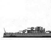
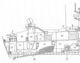


Popular
- Submarines of the Gato type
- Insignia on the merchant fleet of the USSR Detachment of the II group
- How to maximize the speed of your Internet connection Choosing the best browser
- Productive ways to spend time online
- Hiding VKontakte photos
- Tim Berners-Lee - creator of the World Wide Web
- Start in science Net weight of eggs without shell = - - - - - - - - -
- How to delete photos in classmates How to remove tinsel from a photo on classmates
- How to add a photo in a contact?
- Tatyana Gordienko: Other designers copy me and I'm happy about it!