Rolling equipment. Equipment and tools for rolling
The main tool for rolling are rolls, which, depending on the rolled profile, can be smooth (Fig. 3.20, a) , calibrated (stream) (Fig. 3.20, b) and special. Smooth rolls are used when rolling sheets, strips, etc. All types of long products are rolled on calibrated rolls. Special rolls are used in the production of special types of rolled products.
The rolls have a working part (barrel) 1, two necks 2 for installation in bearings and cruciform ends (clubs) 3 for connecting the roll to the drive (Fig. 3.20).
On the working (side) surface of the calibrated rolls there are grooves - streams. The set of streams of a pair of rolls is called a caliber . Each pair of rolls usually accommodates several calibers. Gauges can be open (Fig. 3.20, c) and closed (Fig. 3.20, d).
Rolls necks based on bearings installed in the frame. With the help of a special pressure mechanism, the distance between the rolls can be adjusted. A set of rolling rolls with a bed is called a working stand. The rolling mill consists of one or more working stands and a drive, including an electric motor and a transmission mechanism (Fig. 3.21).
Depending on the design and location of the rolls, the working stands of rolling mills are divided into six groups (Fig. 3.22): duo, trio, quarto, multi-roll, universal and special design.
Duo (two-roll) stands are reversible (rolling in both directions) and non-reversible (rolling in one direction). Trio stands (three-roll) are most often non-reversible. Rolling on such mills is carried out forward between the lower and middle rolls and backwards between the upper and middle ones. Quarto (four-roll) stands have four rolls located one above the other, of which two work rolls of a smaller diameter and two support rolls of a larger diameter. Due to the rigidity and relatively low deflection of the back-up rolls, these stands produce cold rolling of thin strips and narrow strips with a small thickness tolerance. Universal stands have horizontal and vertical rolls: the latter provide metal reduction in the transverse direction. Vertical swaths are located, as a rule, on the front side. Stands of special design include the stands of narrow-purpose rolling mills: wheel-rolling, bandage-rolling, ring-rolling, ball-rolling, rolling mills for rolling profiles of variable section.
According to the type of products produced, rolling mills are classified into the following main types: swaging, billet, rail and beam, section, wire, plate, pipe and special-purpose mills.
Crimping mills are designed for compression of steel ingots into large billets. Crimping mills include blooming mills that produce square profile blanks - blooms and slabs that produce rectangular rolled products - slabs.
Blanking mills are used for rolling blooms into billets, mainly of square section, which are subsequently used for rolling at bar mills.
Rail beam mills are used to obtain rails, large beams, channels and other profiles from blooms.
section mills, used for the manufacture of long products of simple and shaped profiles.
Wire mills designed for rolling wire with a diameter of 5 ... 10 mm.
sheet rolling mills, subdivided into thick and thin sheets. Thick plate mills roll a sheet with a thickness of more than 6 mm. The blanks are slabs.
Tube mills used for the production of seamless and welded pipes.
Special mills are intended for obtaining blanks of special and periodic profiles. Balls, ribbed tubes, wagon axles, gear wheels and many other products of complex configuration are rolled on special mills.
The principles of calibration of the deformation tool in the production of wheels do not differ from general principles tool calibration in the production of other products by stamping or rolling methods.
To design the calibration, it is necessary, taking into account the allowances for machining and changes in the relative position of individual elements as a result of heat treatment, to set the dimensions of the wheel before its mechanical and heat treatment (the so-called rough wheel) and calculate the dimensions of the hot wheel obtained from the last unit of the press-rolling line .
To save metal in the production of wheels, the proportion of tolerance used in calibration and the amount of machining allowance should be as small as possible. At the same time, these values should be realistic, since with extremely small tolerances and allowances that do not take into account the actual state of the surface quality and the accuracy of the geometric dimensions of the wheels, the losses from marriage due to the inability to repair the defect may turn out to be greater than the metal savings due to the reduction permits and allowances. Usually, for the production of wheels according to the technology operating in domestic workshops, 1/2 - 2/3 of the tolerance field is taken to calculate the optimal dimensions of the machined wheel. Improving the methods of obtaining blanks and methods for the production of wheels should be aimed at further reducing tolerances.
To determine the dimensions of the rough wheel, the value of the allowance for mechanical and heat treatment is set. The allowance depends on a number of factors, however, as a rule, one of them is decisive.
The allowance for the outer diameter of the rough wheel should take into account its ovality, the reduction in diameter during heat treatment, but the determining factor for determining the allowance here is the sorting of wheels into marriage by non-metallic inclusions. To determine the optimal allowance for turning the wheel in terms of the outer diameter, it is necessary to compare the losses from marriage, which decrease with an increase in the allowance, and waste into chips, which at the same time increase.
It is necessary to take into account changes in wheel dimensions depending on the heating temperature.
For the outer diameter of the wheel due to its subsequent turning, the high accuracy of determining the hot size is less significant and the greatest practical impact of the accurate determination of the linear expansion coefficient, as well as proper accounting elastic deformation of the tool affects the inner diameter of the rim on the inside of the wheel. The coefficient taking into account the combined effect of temperature and elastic deformation of the bending dies is set to 1.015. Here, the coefficient of linear expansion is taken equal to , and the difference between the temperature of hot deformation in the mill and cooled wheels  .
.
Hot wheel dimensions are equal, mm:
where is the coefficient of linear expansion;
– cold wheel dimensions, mm
The design and dimensions of solid wheels for North American railwaysØ J-33." according to AAR M-107 / M-208-2010, are shown in Fig. 3.1.
Solid-rolled wheel for North American railways Ø J-33"

* Dimensions for reference,
** Dimensions are provided by the tool.
In table. 6 shows the dimensions that are taken when calculating the calibration of solid-rolled wheels for North American railways Ø33".
Table 6
Estimated dimensions of wheel elements
| Name of sizes | Finished wheel dimensions, mm | Draft wheel dimensions, mm | Hot wheel dimensions, mm | |
| Outer rim diameter |  | 848,2 | 861 | |
| Rim inner diameter |   | 768,7 768,7 | 780 780 | |
| Width | Rim Crest |   | 142 32 | 144 33 |
| Ridge height | 26,3 | 26,7 | ||
| Disc thickness | at the rim at the hub |   | 22,1 22,1 | 40,8 40,6 |
| hub diameter | from the outside from the inside |   | 275,9 275,9 | 280 280 |
| Hub length |  | 199 | 202 | |
| hub hole diameter |  | 201 | 204 | |
| protrusion |  | 60,2 | 61,1 | |
Determine the weight and size of the workpiece
The choice of the optimal mass of the initial workpiece contributes to obtaining the dimensions of the finished wheel within the specified limits, facilitates the adjustment of all units included in the hot conveyor, and allows you to quickly establish the technological process. If there are significant deviations from the given optimal mass of the workpiece, there will be deviations in the dimensions of the finished wheels, the elimination of which may require changes in the equipment setup, and in some cases lead to a decrease in productivity.
To determine the mass of the workpiece, we first determine the mass of the rough wheel. The density of the individual parts of the finished wheel can be considered the same, and therefore the determination of the weight of the finished wheel can be reduced to determining its volume.
To determine the volume of the rough wheel, we use a computer application solidworks 2010, where, by drawing its section, we model a three-dimensional image. As a result, we obtain the volume of the rough wheel equal to 62197999.74 mm 3. The extrusion volume on the K5000 press is determined similarly, taking into account thermal expansion, it will be 5277449 mm 3 .
Taking the density of wheel steel grade C equal to 7850 kg / m 3, according to formula (2) we determine the mass of the rough wheel:
 , (2)
, (2)
where M h is the mass of the roughing wheel, kg;
V is the volume of the draft wheel, m 3;
ρ - steel density, kg / m 3.
Taking into account the mass of the extrusion, the waste of metal in the furnace, the nominal mass of the workpiece will be:
The diameter of a continuously cast billet is 430 mm, knowing its volume, we determine the height of the billet by the expression:
 (3)
(3)
Where R– billet radius, mm.
 (mm).
(mm).
We accept the height of the workpiece ![]() mm.
mm.
Calculation of the calibration of the bending press deformation tool.
We calculate the calibration of the hot deformation tool in the reverse order technological process, therefore, first of all, consider the calibration of the bending press deformation tool.
The diameter of the upper dies, which determines the inner diameter of the rim on the outer side of the wheel, is taken equal to the corresponding hot size. The diameter of the upper stamp at a distance of 10 mm from the end of the rim is  . The diameter of the lower dies is set in the same way:
  .
.
To calculate the height TO the peripheral part of the stamps, as well as some of its other dimensions, the following must be taken into account. When the disk is bent, the dies do not contact the wheel over the entire surface. The upper stamp is in contact with the wheel at the disc-to-hub transition, and the lower one is at the disc-to-rim transition. There is a gap between the upper die and the wheel at the disc-to-rim transition area, as well as between the lower die and the wheel at the disc-to-hub transition area, which is necessary due to the tolerance on the thickness of the disc at the rim and at the hub (actually 3 mm). If there was no such gap, then with a thick disk, the stamps would come into contact with it, and rim width calibration would become impossible.
Since the allowance for trimming the rim on the inner and outer sides of the wheel is assumed to be the same, the distance from the axis of the disk to the ends of the rim in the hot wheel is taken:
 (4)
(4)
 (5)
(5)
where is the hot rim width, mm;
t is the distance from the inner end of the rim to the axis of symmetry of the disc (s
taking into account thermal expansion), we take it equal to 76.4 mm.
 (mm).
(mm).
Then, taking into account the previously stated, the height of the peripheral part of the stamps will be equal to:
 , (6)
, (6)
 , (7)
, (7)
where is the thickness of the disk at the rim, mm;
- a gap equal to 6 mm.
 (mm),
(mm),
 (mm).
(mm).
Accept  mm,
mm,  mm.
mm.
The slope of the peripheral part of the stamps is taken according to the wheel drawing:


Similarly, we determine the slope of the cavity of the stamps according to the dimensions of the hub:


In connection with the use of upper and lower solid-bottomed dies (in the lower stamp, the ejector serves as the bottom, and in the upper, the firmware cylinder) calibrating the end of the hub from the outer and inner sides of the wheel, it is necessary to determine the length of the neck of the dies h. This size is determined on both sides of the axis of symmetry along the length of the hub.
 , (8)
, (8)
 , (9)
, (9)
Where Lc- the length of the hub, equal to 196.7 mm;
lc- hub protrusion, equal to 63.5 mm;
t- distance from the inner end of the rim to the axis of symmetry of the disk,
equal to 76.4 mm;
t c is the thickness of the hub at the disk, equal to 37.5 mm.
h V\u003d (63.5 + 76.4) - 37.5 / 2 \u003d 121.15 (mm),
h n= 196.7-121.15-37.5 = 37.7(mm).
The outer diameter of the stamp web is determined from a simple geometric relationship:
 , (10)
where is the diameter of the stamps, mm;
– height of the peripheral part, mm;
– slope of the peripheral part of the stamps.
Calculating by formula (2.7) we get:
Accept  mm, mm. Rounding up is associated with the possibility of a press of greater force to correct the geometric asymmetry of the wheel.
The protrusion of the central part in relation to the peripheral for the upper stamp or, conversely, the peripheral part above the central for the lower, the so-called deflection of the stamp, must provide the required deflection of the disk in the finished wheel. According to the drawing of the wheel, we obtain the following ratios for determining the deflection of the disk from the outside () and from the inside ():
 , (11)
where is the width of the disc at the hub and rim, respectively, mm.
On the wheel blank after the end of the deformation, the protrusion should be smaller, since when the wheel is cooled, and then as a result of heat treatment, it increases by this value. When designing dies, one should also take into account the gaps between the dies webs and the disk, which are necessary for the normal course of the bending process and wheel calibration. Since the hub is stationary when the hole is pierced, there is no additional disc deflection when the hole is pierced. We accept mm.
To determine the diameter of the cavity of the upper stamp under the hub, we calculate the dimensions of this part of the hub in the hot state. The calculated hub diameter of the finished wheel blank at a distance of 10.15 mm from the inside is equal to And in= 312.4 mm, with outer A n = 308 mm (including tolerance and temperature).
The large diameter of the upper die cavity will be:
B in = A in+2h in tg TO, (12)
Where h in- the length of the neck of the upper stamp, equal to 121.15 mm;
TO- the magnitude of the slope of the side wall of the hub, equal to 34 o.
in in\u003d 312.4 + 2 121.15 tg 34 o \u003d 475.8 (mm).
The large diameter of the cavity of the lower stamp is determined similarly, it will be:
V n\u003d 308 + 2 37.7 tg 12 o \u003d 324 (mm).
The diameter of the piercing is assumed to be 173.4 mm, the remaining dimensions, depending on the design of the press, are determined according to the drawings of the Design Bureau of JSC EVRAZ NTMK.
The main dimensions of the bending dies are shown in Table. 7
Table 7
Basic dimensions of bending dies for the production of solid wheels for North American railways Ø33"
Calibration of edge rolls
When calibrating a deforming tool for rolling a wheel, one should not only take into account the individual purpose of a roll or a group of rolls, but also their work on shaping the workpiece in conjunction with each other.
The new wheel-rolling mill has 9 rolls, and the billet is vertical during rolling.
Inclined rolls roll out the wheel blank according to the diameter and smooth out the surface of the wheel disc, which is newly formed as a result of rolling. The working part of the inclined rolls is formed by combining two truncated cones connected by their bases.
To reduce slip between the metal and the roll due to the different linear speeds of points located at different distances from the center of the workpiece, these rolls are set at an angle to the horizontal plane. We accept an inclination angle of 30º for both rolls.
The diameter of the edger rolls (Fig. 2) is taken, taking into account the possibility of regrinding, to be 290 mm for each roll.
The estimated length of the generatrix of the initial cone must be determined from the dimensions of the rim of the hot wheel, which enters the bending press. We calculate the part of the rim under the disk using formulas (3.6) and (2.7) without taking into account the gap δ, taking into account the subsequent calibration of the rim in height (≈2 mm).
 (mm),
(mm),
 (mm).
(mm).
We take the diameter of the roll at the intersection of the initial and end cones equal to 435 mm (taking into account the possibility of regrinding 15 mm during operation).
Edger roll

The angle between the generatrix of the initial cone and the generatrix of the end cone is equal to:  . The angle between the axis of symmetry of the edger roll and the generatrix of the initial cone is equal to:
  , then the angle between the axis of symmetry of the roll and the generatrix of the initial cone will be equal to: .
The length of the generatrix of the initial cone and the length of its projection on the axis of symmetry of the roll are determined from the following geometric relationships:
 , (13)
 , (14)
where is the roll diameter at the intersection of the initial and end cones, mm;
− diameter of the cylindrical part of the roll, mm.
 (mm),
(mm),
The radius of conjugation of the initial and end cones is 26 mm. Then the distance from the cylindrical generatrix of the roll to the point of application of this radius is determined by:
The length of the generatrix of the end cone is determined constructively, while it should be borne in mind that the inclined roll must be placed between the rim and the hub without damaging the hub when the wheel is loaded into the mill and during rolling. Taking into account the possibility of regrinding during operation minimum diameter end cone accept 336.5 mm. Then the horizontal projection of the generatrix of the end cone and the length of the generatrix will be equal:
 , (15)
 , (16)
where is the diameter of the roll at the intersection of the initial and end
cones, mm;
− minimum diameter of the end cone, mm.
 (mm),
(mm),
 (mm).
(mm).
The main dimensions of edger rolls are shown in Table. 3.3, the dimensions of the remaining elements of the edger rolls, necessary for attaching them to the shafts, depend on design features mill and are determined according to the drawings of the design bureau of EVRAZ JSC NTMK.
Edger Roll for the Production of Solid Wheels for North American Railways Ø J-33"

Table 8
Basic dimensions of edger rolls for the production of solid wheels for North American railways Ø J-33"
Determination of the dimensions of conical (side) rolls
The side rollers compress the rim along the width, fixing a certain predetermined size.
The angle at the top of the cone is optimally taken to be 35°, in accordance with the recommendations
The length of the cone (horizontal projection of the web) in accordance with the capabilities of the mill (design dimensions) is taken equal to 399 mm. The rectilinear section on the side surface is taken as 60 mm.
The diameter of the smaller base of the truncated cone (assuming the possibility of regrinding 15 mm) is 217.5 mm.
Then the maximum diameter of the cone, which does not change as the roll is re-sharpened, is 486 mm.
Determine the length of the generatrix of the cone:
 (mm).
(mm).
Determining the size of the pressure roll.
Calibration of the main roll is carried out in such a way as to provide the necessary profile of the tread surface and the crest at the rough wheel, that is, the roll contour completely repeats the tread surface and the crest of the finished rough wheel (Fig. 4).
We take the diameter of the main roll equal to 1300 mm, which is nominal according to the project of the installed mill.
We accept the height of the roll caliber by 10–15 mm more than the width of the rim of the molded blank, that is, 189 mm. The dimensions of the main roll on the surface in direct contact with the workpiece repeat the dimensions of the roughing wheel. We take the width of the roll equal to 198 mm.
The dimensions of the remaining roll elements required for fastening depend on the design features of the mill and are determined according to the drawings of the Design Bureau of JSC EVRAZ NTMK.
The driving rollers are cylindrical in shape: diameter is 280 mm (taking into account the possibility of regrinding 10 mm); width 130 mm.
Pressure roll for the production of solid wheels for North American railways Ø33"

For centering rollers: diameter along the groove 300 mm, in the plane of the tread circle 379.74 mm (taking into account the possibility of regrinding 15 mm); profile slope 2.9°; the remaining dimensions are in accordance with the dimensions of the ridge and the rolling circle of the rough wheel.
Calibration of the forming press deformation tool.
The upset billet enters the molding press for forming a wheel billet from it. On the molding press, the hub and a significant part of the disk adjacent to it are completely formed. In addition, the rim is prepared for subsequent rolling. This determines the configuration and dimensions of the deforming tool press: upper (Fig. 5) and lower dies (Fig. 6); a forming ring for shaping the rim of the workpiece; mandrels.
The deformation tool used in the stamping of wheel blanks consists of dies, a mandrel and forming rings.
The dimensions of the workpiece on the molding press are determined by formula (2.1), taking into account the difference between the deformation temperatures of the workpiece on the molding and bending presses, which is 150 0 C.
The determination of the dimensions of the central cavity of the molding dies is associated with its similar dimensions in the bending dies.
Forming top die

Forming lower die

As it was established above, the length of the parts of the hub protruding above the disk after the bending press is h in=121.15 mm, h n=37.7 mm. Taking into account thermal expansion, some compression of the hub from the inside and the disk in the bending die (0.6 mm and 0.1 mm, respectively), as well as compression of the metal along the height of the disk by edger rolls at the initial moment of rolling (2 mm), the indicated dimensions molding press is determined by the following expressions:
 , (17)
where are the dimensions on the bending press, mm.
Previously, it was shown that the hub diameter of a hot billet wheel at a distance of 10.15 mm from the end of the hub on the inside is equal to And in= 312.4 mm, with outer A n = 308 mm. Then, on the molding press, taking into account the temperature difference, the diameter of the wheel hub at a distance of 10.17 mm from the end face on the inside is equal to And in= 313 mm, with outer A n = 308.6 mm. Taking into account the distribution of the cavity of the stamp, which takes place at the very beginning of its operation, we accept And in= 314 mm, with outer A n = 309.6 mm.
The diameter of the central cavity of the stamp near the canvas is found from the ratio:
 , (19)
where is the slope of the die cavity (for the lower  , for the top
  ).
).
The dies have a slope of 1° to increase the thickness of the disk from the central to the peripheral region, this contributes to the flow of metal into the rim during stamping.
The diameter of the die web should be determined based on the required amount of rolling and the required press force. The optimal value of rolling the wheel in diameter is 174 mm.
Based on the accepted value of rolling and the inner diameter of the wheel, we determine the outer diameter of the dies:
 , (20)
where is the inner diameter of the bending dies, mm;
IN- the value of rolling in diameter, mm.
The height of the peripheral working part of the forming dies should be determined as the sum of the thickness of the part of the wheel rim protruding above the disk and the amount of reduction on the mill. Taking into account the slope and diameter of the disk near the hub, the thickening of the disk near the rim is assumed to be 2.3 mm.
Determine the height of the stamps. Due to the fact that the conical rolls do not have a drive, we set the reduction on the mill along the height of the rim. Experience in the production of wheels in the conditions of the NTMK CWTs shows that the total value of the rim compression along the width of 5 ... 8 mm is sufficient for the complete roll-out of the rim ends on the wheel-rolling mill. And the rational value of the ratio of absolute reductions from the inner and outer sides of the forging, due to the fact that the front tapered roll, due to the narrowing of the rim to the end of the outer side, carries out a greater reduction than the rear is the value  = 0.1…0.3. Let us take the total reduction equal to 3.5 mm, and from the side of the front roll
  mm, and from the rear
  mm.
mm.
Then the height of the peripheral working part of the dies, taking into account the subsequent calibration of the rim in height (≈2 mm), can be determined from the expression:
Where IN− height of the rim sections outside the disk on the bending press, mm;
H− compression, mm;
- the difference in the thickness of the disk at the hub and at the rim after
wheel rolling mill, mm;
− reduction of metal along the height of the disc by edger rolls to the initial
rolling moment, mm
We get for the top and bottom stamps:
The slope of the peripheral zone to improve the deformation conditions, taking into account that the shape of this section will be finally formed on the mill and the bending press, is taken equal to γ = 20º, and the radius of conjugation of the peripheral cone with the canvas of the upper and lower dies is 37.5 mm each.
The diameter of the web of stamps is determined from the ratio:
To determine the dimensions of the forming ring, we use the following data. The ring must provide preliminary shaping of the wheel rim and flange: the width of the rim and flange, taking into account the subsequent reduction by tapered rolls (sides of the front roll  mm, and from the rear
  mm); the required radii of the ridge-to-rim interface (except for the interface of the ridge to the inner end of the rim); the required slope of the outer surface of the rim (take 7 0); slope of the ridge surface 20 0 . Taking into account the above, we will determine the dimensions of the surface of the molding ring in contact with the rim.
The width of the ridge is determined from the expression:
 , (23)
Where b− crest width on the bending press, mm.
The width of the rim can be determined, taking into account the subsequent calibration of the rim in height on a bending press (≈2 mm), similarly:
Where h− width of the rim on the bending press, mm.
The dimensions of the molding dies are given in table. 2.4. The dimensions of the press mandrel are fully determined by the dimensions of the hole in the hot wheel hub. We take the height of the mandrel of the lower stamp to be 42.8 mm, and the upper one 108 mm, the rest of their dimensions are determined according to the drawings of the design bureau of EVRAZ NTMK JSC.
Table 9
Dimensions of forming dies for the production of solid wheels for North American railways Ø J-33"
| Size | Upper Stamp | bottom stamp |
| External diameter, mm | 653 | 653 |
| Peripheral part: slope, deg. fillet radius | ||
| 65,7 | 54,7 | |
| 20 | 20 | |
| 37,5 | 37,5 | |
| Die sheet, mm: | ||
| 605,2 | 613,2 | |
| Die hub height | 36,72 | 120,34 |
| Die end cavity diameter | 309,6 | 314 |
| Large die cavity diameter | 365,6 | 360,6 |
| Slope, deg. | 12 | 34 |
The dimensions required for fastening stamps to stamp holders are determined according to the drawings of the Design Bureau of EVRAZ NTMK JSC.
Calibration of the crimper deformation tool.
The workpiece after descaling at the water descaling unit enters the swaging press.
Deformation on the press is carried out as follows. The workpiece is fed to the crimping table and centered, and then there is a crimping in the calibration ring. Without being fixed on the crimping table, the calibration ring can move under the pressure of the deformable workpiece and thus assume a position concentric with respect to the workpiece (floating ring).
The casting of the cast billet on the press is carried out using interchangeable flat plates attached to the table and the upper stamp holder, and the dimensions of which depend on the design of the stamp holder and are shown in the drawing.
The diameter of the upset workpiece - "buns" - must be greater than the diameter of the die of the molding press - in order to avoid the formation of clamps at the points of mating of the pressure surfaces of the dies with their side surface. The diameter of the bun should be close to the diameter of the forming ring in order to ensure the impact of the forming ring in the first stamping period and thereby ensure that the central cavity of the die is filled with metal. At the same time, an excessive increase in the diameter of the bun can lead to the formation of clamps at the transition point from the rim to the disk of the wheel blank. This will happen due to the displacement of the metal of the bun in the outer cavity from top to bottom under the pressure of the forming ring.
The optimal compression during disk formation is ≈ 85 mm, therefore, the height of the bun in front of the molding press should be about 123.3 mm. The height of the gauge ring should be slightly less than the height of the upset workpiece to be able to control the degree of deformation.
The slope of the calibration ring will take 20 0 . To determine the diameter of the calibration ring, we will assume that in cross section the “bun” is a trapezoid with a height of 123.3 mm. Then the area of the trapezoid F can be defined:
 , (25)
Where a 1 – half sum of bases, mm;
H-"bun" height, mm.
According to the second Guldin–Papp theorem, the volume of a body formed during the rotation of a figure lying in a plane entirely on one side of the axis of rotation is equal to the product of the area of the figure and the length of the circle traversed by the center of mass of this figure.
Then, with a sufficient degree of accuracy, the volume of the bun (Fig. 3.9) can be taken equal to:
 (26)
(26)
The half-sum of the bases of a trapezoid can be determined by the following expression:
 (27)
(27)
 (mm).
(mm).
Inner diameter of the calibration ring at the base of the upper die D min is determined from the expressions:
 , (28)
Where α - the angle of inclination of the forming ring, equal to 20 0 .
 (mm).
(mm).
The height of the gauge ring should be slightly less than the height of the upset workpiece to enable the degree of upset to be controlled; let's take the height of the ring as 99 mm. The dimensions of the outer diameter of the calibration ring are selected taking into account its free movement in the tooling. Other dimensions of the deformation tool are determined according to the drawings of the Design Bureau of EVRAZ JSC NTMK.
ROLLING PRODUCTS
form cross section rolled strip is called profile. The set of shapes and sizes of profiles obtained by rolling is called assortment . In DSTU, the cross-sectional area, dimensions, weight of 1 m of the length of the profile and permissible deviations from the nominal dimensions are given for the range of rolled products. The assortment of rolled profiles is divided into four main groups : long products, sheets, pipes and special types of products.
Long products are divided into profiles simple geometric shape (square, circle, hexagon, rectangle) and shaped(channel, rail, corner and tee profiles and round and square steel are rolled, respectively, with a diameter or side of a square of 5-250 mm; hexagonal - with an inscribed circle diameter of 6-100 mm; strip - with a width of -200 mm and a thickness of 4-60 mm. Non-ferrous metals and their alloys are rolled mainly into simple profiles - round, square, rectangular.Sheet steel is divided according to its purpose into autotractor, transformer, roofing tin, etc. According to the type of coating, sheet steel is divided into zinc-coated, aluminum, plastic coated, etc. In addition, sheet steel is divided into thick sheets with a thickness of 4-160 mm) and thin sheets (less than 4 mm thick), with a thickness of less than 0.2 mm, called foil. Pipes are divided into seamless and welded. Seamless pipes are rolled with a diameter of 30-650 mm with a wall thickness of 2-160 mm from carbon and alloy steels, and welded pipes - with a diameter of up to 2500 mm with a wall thickness of 0.5-16 mm from carbon and low-alloy steels. Special types of rolled products include wheels, balls, periodic profiles with a periodically changing shape and cross-sectional area along the axis of the workpiece. .
Rolling tools are rolls, which, depending on the profile being rolled, can be smooth, used for rolling sheets, strips, etc., stepped, for rolling strip steel, and grooved, to obtain long products. A stream is called a cutout on the side surface of the roll, and the combination of two streams forms a caliber . Each pair of stream rolls usually forms several calibers. A set of rolling rolls with a bed is called a working stand; the latter, together with the spindle for driving the rolls, a gearbox, couplings and an electric motor, form the working line of the mill. According to the number and arrangement of rolls, the working stands can be two-roll four-roll, which have 2 work rolls and two support rolls; multiroll , which also have two rolls of workers, and the rest - support. Rolling mills can be single-stand (with one working stand) and multi-stand. The most advanced multi-stand mills are continuous, in which the working stands are arranged sequentially one after the other. The rolled strip passes through each stand only once, i.e. the number of working stands of these mills is equal to the required number of strip passes. Max speed rolling on continuous mills is 50-60 m/s. By appointment Rolling mills are divided into mills for the production of semi-finished products and mills for the production of finished products. The first group includes swaging mills for rolling ingots into a semi-finished product of a large section (blooming, giving a blank for long products, and slabs, giving a blank for sheet metal) and blanks for producing a semi-finished product of a smaller section. , pipe and special. The size of blooming, slabbing, billet and section mills is characterized by the diameter of the roll barrel (for example: blooming 1500; section mill 350); the size of sheet mills - the length of the barrel (for example: mill 3600), and the size of pipe mills - the outer diameter of the rolled pipes.
Classification of rolling mills
A rolling mill is a complex of machines and units designed to carry out plastic deformation of metal in rolls (rolling), its further processing (straightening, cutting, etc.) and transportation.
In the future, a rolling mill will be called equipment designed only for metal deformation.
Rolling mills are usually classified according to three main features:
- purpose or type of manufactured products;
- the location of the rolls in the working stand;
- the location of the working stands.
Depending on the purpose, rolling mills are divided into the following groups.
hot rolling mills, which include swaging, billet, rail and beam, large-section, medium-section, small-section, wire, thick-sheet, medium-sheet, thin-sheet, broadband and strip (producing strip blanks for pipes in the form of a strip).
Cold rolling mills, including sheet, tin rolling mills, as well as mills for rolling thin and thin strip.
Special Purpose Mills, which include wheel-rolling, bandage-rolling mills, mills for rolling strips and profiles of variable and periodic section, etc.
According to the design and arrangement of the rolls of the working stand, rolling mills can be divided into six groups (Fig. 4.10): two-roll, three-roll, four-roll, multi-roll, universal and special design stands.
Rice. 4.10. Working stands with different arrangement of rolls: A - two-roll stand; 6 - three-roll milled stand; V- three-roll stand Lauta sheet; g - four-roll sheet non-reversible stand; d- four-roll reversible stand for strip rolling in rolls; e- six-roll cage; and - twelve-roll stand; h - twenty-roll stand for thin strip rolling; And- universal two-roll stand; To- universal stand for rolling I-beams with wide parallel flanges
Two-roll stands (duo)(Fig. 4.10, A) there are irreversible And reversible. The first type of stand has two drive rolls with a constant direction of rotation. Such stands are realized in continuous mills used for rolling blanks, wire, thin strips, etc. In each stand of these mills, only one pass of metal is performed in one direction. Reversible stands have two drive rolls with reverse rotation, so the rolled metal passes through the rolls back and forth several times. The disadvantage of such stands is the need for energy costs for the reverse operation, which consists in braking the rolls, and then in their acceleration in the opposite direction. Cages of this type are used in blooming, slabbing, plate mills, etc.
Three-roll stands (trio)(Fig. 4.10, b)- irreversible and can be used for both section and sheet rolling. High-quality stands are widely used, since more calibers can be placed on three rolls than on the rolls of two-roll stands. The metal moves in one direction between the lower and middle rolls and in the other - between the middle and upper.
Sheet three-roll stands ( Laut's cage)(Fig. 4.10, V) used for rolling thick and medium sheets in the form of strips 10-20 m long. The middle roll is non-driven and has a smaller diameter. During rolling, it is pressed alternately against the upper and lower rolls and rotated by them due to friction forces. Both types of mills are equipped with oscillating tables for feeding workpieces between different pairs of rolls.
In the working four-roll stand (quarto)(Fig. 4.10, G) rolls are located one above the other: two work rolls of smaller diameter (medium) and two support rolls of larger diameter, their purpose is to take the pressure during rolling and reduce the deflection of the work rolls. Mills with such stands can be reversible and non-reversible. They are used when rolling thin and thick sheets and strips, armor plates, and rolls.
Cold rolling of rolls is carried out on continuous non-reversing mills. In this case, a roll unwinder is installed in front of the stand, and a winder is installed behind it, creating strip tension and winding it onto a drum (Fig. 4.10, 0). During cold and hot rolling of coils on single-stand reversing mills, winders are installed on both sides of the stand, and rolling takes place first in one direction, then in the other. Sometimes, during hot rolling, coilers are installed in furnaces in front of the stand and behind it.
Six-roll stands (sixta)(Fig. 4.10, e) with two work and four back-up rolls, due to the rigidity of the work stand itself and the smaller deflection of the back-up rolls, they are used for cold rolling of thin strips and narrow strips in coils with precise thickness tolerances. However, the advantages of this type of stands compared to four-roll stands are insignificant, and since their design is more complicated, they are not widely used.
Twelve- And twenty-roll(Fig. 4.10, and, h) stands are used for foil rolling. Due to the use of rolls of very small diameter (10-35 mm) and high rigidity of the entire working stand and roll system, these mills successfully carry out roll rolling of thin and very thin strip with a thickness of 5-100 microns and a width of 100-1500 mm with a thickness tolerance of 1- 5 µm. The work rolls of such mills are not driven, as they have a too small diameter; they rest on drive rolls of larger diameter, and the latter, in turn, on support rollers. This scheme provides greater strength of the entire roll system and practically complete absence deflection of work rolls.
Stands with horizontal and vertical rolls are called universal. Universal stands (ordinary) are mainly used as reversible two-roll (for example, for slabs) (Fig. 4.10, And) or four-roll (for example, for plate mills). On these stands, the metal is reduced by both horizontal and vertical rolls. Vertical rolls ensure the creation of even and smooth side faces of sheets and slabs. Such rolls are located, as a rule, at one side of the working stand. In universal beam stands (Fig. 4.10, To), unlike conventional, vertical rolls are non-driven. These mills are used for rolling high I-beams with wide flanges.
Stands of special design used in narrow-purpose mills: wheel-rolling, bandage-rolling, ring-rolling, ball-rolling, mills for rolling profiles of variable and periodic section, etc.
Depending on the location of the working stands, rolling mills are divided into five groups: single-stand, linear multi-stand, sequential, semi-continuous, continuous (Fig. 4.11).
Single stand mills(Fig. 4.11, a) have one working stand with a roll drive line, consisting of spindles, a gear stand, a gearbox, couplings and the main electric motor. Single-stand reversing mills are versatile and convenient for reconfiguring from one program to another. The advantage of such mills is a small footprint. The disadvantage is the additional consumption of energy and time for reverses. These mills include blooming, slabing, thick plate three- and four-roll mills, as well as universal mills.
Working stands linear mills (Fig. 4.11, 6) located in one, two, three or more lines, each line is powered by a separate drive, or several lines - from one electric motor. Mills of this type are non-reversible; they are used as wire, high-quality, rail-and-beam and thick-sheet.
IN successive mills (Fig. 4.11, V) the rolled strip passes several times through each stand, so the number of stands of such a mill is equal to the maximum number of passes required to reduce the workpiece with a section P 0 into a finished profile with a section / ^ 1 To reduce the length of the workshop and better use its area, the stands are usually arranged in several parallel rows. The mills of this group have high productivity, therefore they are widely used for rolling profiles.

Rice. 4.11. Layouts and drive of working mills: A - single-cell; b - linear; V - sequential; G - semi-continuous; d - continuous;
1-13 - working stands
semi-continuous mills (Fig. 4.11, G) consist of two groups of stands: continuous and linear. In one group of stands, the strip is rolled continuously, i.e., it can be simultaneously in two or more stands. In the other group, rolling is carried out according to the principle of linear and sequential mills. These mills are used for rolling small grades of wire and strips.
When rolling on continuous camp (Fig. 4.11, e) the metal is simultaneously in several stands, so the speed of rotation of the rolls in the stands must be regulated and selected so that the metal consumption per unit time in any stand is constant:
F = F 2 v 2 = .. .F „j n = const, (4.43)
Where F, F2, Fn- cross-section of the metal at the exit from the first, second and last stands; x>, o 2,..., o" - the speed of the strip at the exit from the rolls of these stands. Irreversible continuous mills are high-performance units designed for mass rolling of one nomenclature (size). Continuous mills are used as billet, broadband, small section, wire and cold roll mills for sheet and tin. The roll drive of these mills can be group or individual.
For the production of rolled products in rolling shops, mills are installed various types and appointments, which are conditionally divided into several groups.
Billet mills: blooming, slabing, continuous billet mills. Bloomings and slabs - these are large swaging mills with a roll diameter of 800-1500 mm, in which rolling is carried out in 11-15 passes in reverse mode. As a rule, these are single-stand mills for the production of large billets in the form of a rectangular billet (slab) and a square billet (bloom). Bloomings are single-stand two-roll and multi-stand, reversible and continuous. Single-stand, two-roll reversible blooming mills are most widely used as billet mills for rolling blooms and slabs. Depending on the diameter of the rolls, large blooming mills (1100–1500 mm), medium blooming mills (900–1000 mm), small blooming mills (800–900 mm) are conditionally distinguished. Continuous blank mills are installed directly behind the blooming (slabing) and usually have two continuous groups of six stands each.
The mills for the production of finished rolled products include: sectional, sheet, pipe and special.
Section mills include large-section, rail-and-beam, medium- and small-section mills. According to their purpose, they are divided into two groups: general purpose, producing a wide range of long products for all branches of engineering and construction, and specialized mills designed for the production of high-quality metal of a relatively narrow assortment used only in certain industries.
On high-section mills produce rolled products with a cross-section in the form of a circle with a diameter of more than 50 mm, as well as squares, corners, channels and other profiles of equal cross-sectional area. On mid-range- profiles of circular section with a diameter of 30 to 50 mm and other profiles of equal area. On small section mills produce rolled products having a diameter of 10 to 30 mm, and other equal profiles. These mills can also include specialized wire mills that produce round products (rolled wire) with a diameter of 5.0-8.0 mm.
Large varieties the mills have finishing stand rolls with a diameter of 850-500 mm, mid-range 500-350 mm, small-grade 350-250 mm and wire 280-150 mm.
Rail beam In addition to the main products (rails and beams), the mills also produce other large section profiles.
TO sheet mills include mills for rolling thick and thin sheets (coiled) rolling. On bandpass or strip mills produce strip for pipe welding units.
TO pipe mills include piercing, rolling mills and cold rolling mills for pipes (CPT), as well as mills for producing welded pipes. Special mills include mills for rolling periodic bent profiles, ball-rolling, wheel-rolling, etc.
The main deforming tool of each rolling mill are rolls rotating in bearings installed in the working stands. The rolls are driven by an electric motor through intermediate transmission mechanisms and devices. The equipment that drives the rolls into rotation, and also perceives the forces and torques arising from the plastic deformation of the metal, constitutes the working line of the stand (Fig. 4.12).
11 1

Rice. 4.12. Scheme of the main line of the four-roll working stand of the sheet rolling mill: 1 - working stand; 2 - universal spindles; 3 - electric motor (main drive); 4 - gear cage; 5 - reducer; 6 - motor coupling; 7 - root clutch; 8 - spring balancing device of spindles; 9 - support non-drive rolls; /0-working drive rolls; 11-
bed; 12 - plate; 13 - anchor bolt
The equipment included in the working line is divided into three main groups:
- working stand 1 with rolls 9,10 and bed 11;
- transmission mechanisms 2, 4-7;
- main motor 3.
Working stand consists of two massive beds mounted on steel plates (plates) 12, attached to the foundation with anchor bolts. The bed of the working stand perceives all the forces arising from the rolling of the metal, and therefore is massive (60-120 tons or more). The bed material is cast steel. For section mills, prestressed working stands are used, in which the increase in rigidity is achieved not by increasing the mass of the frame, but by using special tightening mechanisms. Cushions with bearings and rolls are mounted in the beds, as well as devices for moving the upper roll in height and its axial fixation, guide wires for metal, etc.
transmission mechanisms And devices depending on the purpose and design of the rolling mill can be different. On large mills (crimping, thick plate), as well as on mills that roll metal at high speed, an individual drive of work rolls from separate electric motors is used: in this case, universal spindles, intermediate shafts and couplings are the transmission device. On the rest of the mills, a common drive of the work rolls is provided from the gear stand 4, which is a gearbox, and the role of gears is performed by gear rolls. In this case, between the electric motor and the working stand, a motor coupling is located in one line 6, gear cage 4 and universal spindles.
Spindles- these are connecting parts, thanks to which the torque is transmitted from the gear stand to the rolling rolls. The end parts of the spindles (heads) come in various shapes; the most widely used spindles with universal and club heads. If the angular speed of rotation of the electric motor does not correspond to the speed of rotation of the rolls, then a gearbox 5 and a main gear coupling 7 are installed in the drive line of the rolls.
Main motor rolling mill is air-cooled, can be direct and alternating current, synchronous and asynchronous. DC motors are installed on reversing mills and mills with a wide range of changes in the number of revolutions of the rolls, asynchronous AC motors are used when the operation of the rolling mill does not require a change in the number of revolutions of the rolls over a wide range.
Auxiliary equipment of rolling mills is used to supply metal from heating devices to the receiving roller table of the mill (ingot carriers), turn the ingot on the roller table (rotary devices), transport metal (roller tables or conveyors), move metal along the roll to feed it into the caliber (manipulators), turn metal relative to its longitudinal axis (rotators), metal cooling (refrigerators), metal pickling (pickling plants), coil unwinding (decoilers), strip winding into a coil or wire into a riot (winders), metal cutting (scissors and saws), as well as for metal finishing: straightening (straightening machines and presses), training, branding, laying, oiling, packaging, etc.
Automation of large rolling mills consists of a number of local systems assembled to control the entire course of the technological process. Automation of rolling production starts from the supply of raw material to the warehouse and from the warehouse and ending with the receipt of rolled products at the warehouse of finished products and loading it into wagons. Each system has numerous and diverse sensor devices that collect and transmit information about the course of the technological process, including metal temperature, metal pressure on the mill rolls, parameters of the material being processed, in particular, the dimensions of the rolled profile, its position and the nature of movement. All this information enters the computers of the systems, after which commands are issued to control the machines and mechanisms of the rolling mill related to these
machine that combines individual systems, for the appropriate adjustment of the operation of machines and mechanisms of other sections of the mill, controlled by other systems. One of the main tasks of automation (and the most economically advantageous) is the automation of the regulation of the dimensions of the rolled profile, carried out by a corresponding automatic change in the space between the rolls based on the readings of a continuously operating profile size meter. Due to this, the accuracy of the dimensions of the profile, the quality of the metal is sharply increased, and the specific consumption of the metal is reduced. A particularly great effect is achieved in the production of thin-sheet products.
The main tool for rolling are rolls that perform the main rolling operation - deformation (compression) of the metal and giving it the required cross-sectional shape. In the process of deformation of the metal, the rotating rolls perceive the pressure that occurs during rolling and transfer this pressure to the bearings. Rolls of rolling mills are divided into two main groups: sheet and sectional.
The rolling rolls of sheet rolling mills have a smooth barrel (Fig. 4.13, A), they are installed in a stand on two supports, which is the most common type of roll attachment.
The main parts of the roll:
- barrel- deforming part of the roll with a diameter ABOUT and length
- neck- has a diameter s1 w, length / w and serves as a support area for installing the roll in bearing assemblies;
- end sections are intended for connection with spindles and may have a different configuration depending on the design of the spindle (clubs, blade or cylindrical part).

Rice. 4.13. rolling rolls: A- sheet; b- varietal
The diameter of the roll, which corresponds to the speed of the output of the roll from the rolls (without taking into account the lead), is called rolling diameter. When rolling metal in sheet rolls, the rolling diameter is taken according to a smooth barrel, and for sectional rolls this parameter is determined by formulas that include the dimensions of the roll and caliber. The main parameter of the sheet rolling mill is the length of the roll barrel. This size is used to designate the grade of the rolling mill. For example, the brand "broad strip mill 2500" means that this mill has a smooth barrel length of 2500 mm. This will make it possible to produce flat products with a width of up to 2,500 mm on this mill.
The barrel of rolls intended for hot rolling of thin sheets is made slightly concave so that when rolling hot metal and a large heating of the middle part of the rolls, their barrel becomes cylindrical, and then the thickness of the rolled sheet will be uniform over its entire width. On the contrary, the barrel of rolls for cold rolling of thin sheets is made slightly convex: during rolling, due to the greater bending of the middle part of the rolls compared to the edges, the barrel will become cylindrical.
Varietal rolls (Fig. 4.14, 6) are used for rolling section profiles. On the surface of the barrel of the rolls there are streams corresponding to the rolled profile. The streams of two or more rolls form calibers, therefore the rolls are also called calibrated. The main parameter of the profiled roll is its diameter, which is included in the designation of the rolling mill. For example, the Blooming 250 mill is designed for section rolling and has a roll barrel diameter of 250 mm.
The roll (Fig. 4.13) consists of several elements: a barrel (diameter?) And a length T b), which, when rolling, comes into contact with the metal, necks (diameter s1 w and length / w) located on both sides of the barrel and resting on the roll bearings; the ends of the roll, which serve to connect the roll to the spindle.
The main dimensions of the roll (diameter and length of the barrel) depend on the range of rolled products. Roll diameter for hot rolling ranges from 250-300 mm (wire rolling) to 1,000-1,400 mm (bloom and slab rolling). For cold rolling, rolls with a diameter of 5 mm (on 20-roll mills when rolling foil) to 600 mm (on four-roll mills when rolling thin strips) are used.
The quality of the rolls determines the normal operation of the mill, its productivity and the quality of the rolled products. The rolls are operated under conditions of continuous abrasion by metal during rolling, they experience significant pressures and sometimes operate at high, sharply changing temperatures. Rolls are made of steel and cast iron. Cast iron rolls are characterized by reduced strength, but at the same time they have high wear resistance, therefore they are used mainly in finishing and finishing stands, and sometimes in intermediate groups of stands. Ordinary steel and cast iron rolls do not always meet the increased requirements for them, so it became necessary to use cast and forged high-strength steel rolls and high-strength cast iron rolls. The choice of material for the rolls must take into account the type of rolling mill. For example, during hot rolling on blooming, the rolls are affected by high pressures and temperature. Therefore, such rolls are made of cast or forged carbon steel with high toughness. They are characterized by good resistance to bending loads that occur during rolling. The hardness of the rolls does not play a major role. For cold rolling mills, it is advisable to use alloyed steel and cast iron rolls, in which the surface layer is characterized by high hardness. So, for rolls with a diameter of less than 300 mm, steel grades 9X and 9XP are used, and for rolls with a diameter of more than 300 mm, steels 9X2, 9X2MF, 9X2V, etc. are used. Rolls for cold rolling, made from steel of all grades, are subjected to heat treatment(hardening, tempering) according to special modes. An increase in the strength and hardness of the roll barrel is also achieved surface hardening. The depth of the layer of increased hardness should be in the range of 20-60 mm, which makes it possible, when the surface of the barrel is worn, to produce a large number of regrindings and thereby extend the service life of the roll. An important role in rolling is played by the coefficient of friction on the surface of the rolls. Steel rolls have an increased coefficient of friction, so they are more often used in stands with high reductions. In blooming, slabbing and billet mills, to increase the coefficient of friction and, consequently, improve the conditions for gripping the metal with rolls, surface knurling of rolls with smooth or knurled rollers is used.
Rolling tool are rolls, with the help of which ingots and other blanks are processed. Rolls are:
smooth for rolling sheets, tapes;
stepped for rolling strip steel;
stream to obtain long products.
The cut profile on the side surface of the roll is called creek. The stream of the upper and lower rolls together form caliber.
Several calibers are placed on each pair of rolls, the shape of which depends on the rolled profile. Complex rolled profiles are obtained by successive passages of metal through a series of calibers. For rails, the number of gauges is 9; for beams, from 9 to 13; for wire, from 15 to 19.
Depending on the stage of rolling, there are crimping gauges ( reducing the cross section of the workpiece), draft(approximating the section of the workpiece to a given profile) and finishing or finishing(giving a given profile).
Equipment where metal is rolled is called a rolling mill. Working principle of rolling mill next: rolling rolls are mounted in bearings located in the racks of the frame. A set of rolls together with a bed is called a working stand. The work rolls are rotated by the engine through a gearbox, which transmits rotational motion through the gear cage and spindles.
The rolling mill also includes auxiliary machines and mechanisms that perform auxiliary operations for cutting, finishing and transporting the rolled metal.
§ 3. Classification of rolling mills
Mills are classified according to 3 main features:
by appointment;
according to the number and arrangement of rolls in the working stands;
3. according to the number and location of working stands.
By appointment mills are divided into 2 main types:
mills for the production of intermediate products;
mills for the production of finished products.
To the first type relate crimping and blank mills. Crimping mills - bloomings and slabs with a roll diameter of 800–1400 mm - designed for rolling ingots into large billets (blooms and slabs), which are fed as semi-finished products for subsequent rolling into smaller billets or to obtain a finished product. Billet mills with a roll diameter of 450–750 mm are designed for rolling blooms into billets of smaller sizes (from 50  50 mm to 150
  150 mm), which are the starting material for further rolling on section mills.
To the second type of mills include:
1. rail and beam with rolls with a diameter of 750 - 900 mm for rolling
railway rails, I-beams, channels, angles
large sizes;
2. large sections with rolls 500–750 mm in diameter for rolling large sections steel (square and round from 80 to 150 mm), beams and channels 120–140 mm;
3. medium sections with rolls 350–500 mm in diameter for rolling medium section steel (square and round 40–80 mm), beams and channels up to 120 mm high;
4. small sections with rolls with a diameter of 250–350 mm for rolling small sections (square and round 8–40 mm), angular sections 20  20 to 50
  50 mm;
5. wire mills with rolls 250–300 mm in diameter for rolling wire (wire rod) 5–9 mm in diameter;
6. strip (strip) mills with rolls 300–400 mm in diameter for rolling strips 65–500 mm wide and 1.5–10 mm thick;
7. thick plate mills for rolling sheets 4–60 mm thick;
8. thin sheets of hot and cold rolling for sheets 0.2–4 mm thick and 500–2500 mm wide;
9. universal mills for rolling universal strips 200–1500 mm wide;
10. pipe mills for the production of seamless and welded pipes;
11. special purpose mills - wheel and bandage rolling, ball rolling, etc.
As can be seen from the above classification, the main characteristic of section mills is the diameter of the work or gear rolls. If the mill has several stands, then the characteristic of the entire mill is the diameter of the finishing stand rolls. For example, a wire mill of 250 means that the diameter of the work or pinion rolls of the finishing stand is 250 mm.
According to the number and location of rolls in the working stands of the mill distinguish:
duo-mills - (two-roll) with two rolls in each stand, located horizontally one above the other in a vertical plane.
Duo mills can have a constant direction of rotation of the rolls (irreversible) and variable (reversible). In the latter case, the rolls periodically change the direction of rotation and the ingot or strip passes back and forth between the rolls several times; both rolls are usually driven. Reversible duo-mills have become more widespread: blooming, slabing, thick-plate, etc.
Trio-mills, in which three rolls are located horizontally one above the other in the same vertical plane. The strip is rolled first between the lower and middle rolls, and then with a special device (lifting and oscillating tables) it rises to the level of the middle and upper rolls and is rolled between the middle and upper rolls during the reverse course. Sectional metal and sheets are rolled on trio-mills. Sheet trio mills have an average non-drive roll of a slightly smaller diameter than the upper and lower ones, and on high-quality rolls - all rolls of the same diameter.
quarto-mills have four rolls, vertically located one above the other, two rolls of smaller diameter (middle) are working, and large (upper and lower) are support rolls. The back-up rolls take up the rolling pressure and reduce the deflection of the work rolls. Quarto mills are reversible and non-reversible. They are designed for rolling sheets and strips.
multi-roll mills are six-roll, twelve-roll, twenty-roll, etc. These mills have two work rolls of small diameter, and the rest are support rolls. In view of the small deflection of the work rolls, these mills are used for cold rolling of thin strips and narrow strips in rolls.
universal mills that have vertical and horizontal rolls in one working stand. On these mills, the metal is compressed in width and height. Universal mills are used for rolling strips called universal steel.
According to the number and location of working stands rolling mills separate on single-cell and multi-cell. The simplest type is a single-stand mill. These include blooming, slabing, thick plate duo- and trio-mills, universal mills.
Multi-stand mills have two or more working stands. The location of the cages can be: linear, sequential and continuous. In these mills, each working stand or group of 2–4 stands has a roll drive line.
Linear mills with the arrangement of working stands in one line are rail and beam mills and heavy-section mills.
The most common type of modern multi-stand mills are continuous mills, in which the number of working stands is equal to the required number of passes; rolling is carried out according to the principle - in each stand there is one pass. The stands are arranged sequentially one after the other so that the strip is simultaneously located in two or more stands. The rolling speed in each working stand increases as the section of the rolled strip decreases, which is achieved by changing the number of revolutions of the rolls with an individual drive of the rolls of each working stand, or by changing the gear ratio and the number of revolutions of the rolls and the diameter of the working rolls with a group drive.
Continuous mills are used as blank, section, wire, strip (strip), sheet for cold and hot rolling. The rolling speed on these mills reaches 30–35 m/s and more, due to which continuous mills have high productivity.
-
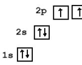 Electronic configuration of an atom
-
 How to connect electricity to the house and the plot: where to go, what you need and how much it costs How to choose a Wi-Fi adapter for a computer: external and internal
-
 How to decorate an office, study or workplace for the New Year: original ideas Decorate an office for the New Year
-
 DIY Christmas decoration
Popular
- Celebration of the day of agriculture and processing industry
- When is Agriculture Day celebrated?
- Card games at the table
- Funny and funny contests for a fun company of adults
- Polish "paratroopers" for the Soviet marines
- Project 205 missile boats
- How is life on the new Chinese destroyer
- The newest frigate "Admiral of the Fleet Kasatonov" is preparing for the first tests and going to sea Ship Admiral Kasatonov
- Submarines of the Gato type
- Insignia on the merchant fleet of the USSR Detachment of the II group