Universal circular saw tspa 40. Rationale for the choice of equipment
29.04.2018
Administrator Chief
The manufacturer of the TsPA-40 circular saw is the Ussuriysk Machine-Building Plant.
Enterprise CJSC Ussuriysky machine building plant ceased to exist in 2014.

The linear guide of the saw unit limits the width of the workpiece to its own length only. So, in the TsPA-40 model, the saw support stroke reaches 400 mm. In order for the device to move in one direction - the direction of saw feed, the caliper has several types of rollers. And the shape of the guide itself is quite complicated. It is subject to intense wear, contact and bending loads, as it has a cantilever shape.
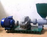
TsPA-40 Cross-cutting circular saw with rectilinear movement of the caliper. Purpose, scope
The machine circular saw with a rectilinear movement of the support of the model is designed for transverse sawing of boards, beams and shields, and can also be used for cutting grooves.
The machine is equipment general purpose for woodworking industries.
The machine has two electric motors:
- Saw blade drive motor 3.2 kW
- 2.2 kW hydraulic pump drive motor
The support rests on rolling bearings and, at the beginning of work, can be manually raised and lowered by means of a handwheel and a gear train. After lifting or lowering the caliper is fixed at a certain height.
During operation, the caliper performs reciprocating movements by means of a hydraulic drive. An electric motor with a cutting disc on the shaft is mounted in the head part of the caliper.

Landing dimensions of the shaft of the TsPA-40 trimming machine

TsPA-40 Location of the components of the trimming machine

List of components of the TsPA-40 trimming machine:
- Caliper Feed Control Pedal Caliper Raise and Lower Handwheel
- Height caliper clamp
- Transport rollers
- Saw blade protection
- Circular Saw
- saw blade shaft
- Thrust bar
- caliper
- Caliper supply hydraulic cylinder
- caliper support body
- Machine bed
- Electric motor - hydraulic pump drive
TsPA-40 Location of trimming machine controls

Kinematic diagram of the TsPA-40 trimming machine

The device and description of the components of the machine
The TsPA-40 cross-cutting machine is simple in design and reliable in operation, provided that all the requirements set forth in this manual are met.
On the frame - a hollow cast iron casting, which is also an oil reservoir, a caliper support body is mounted. The body together with the caliper, if necessary, can be raised and rotated by a certain amount. The caliper rests on rolling bearings and performs reciprocating movements by means of a hydraulic drive. An electric motor with a cutting tool on the shaft is mounted in the head part of the caliper.
The machine is controlled remotely by means of a pedal
Electrical circuit diagram of the TsPA-40 trimming machine

The wiring diagram of the TsPA-40 machine provides for remote control of the machine's electric motors using a push-button station.
The machine is connected to the mains by turning on the machine B.
The inclusion of electric motors Ml, M2 is carried out by the KnP button using magnetic starters P1 and P2.
The stop of the electric motors is carried out by the KNS button, which breaks the control circuit. The starters P1 and P2 are turned off, while the normally closed auxiliary contact P1 closes, the starter R3 is activated and a direct current is applied to the motor windings Ml - dynamic braking occurs.
After a certain period of time, the electrical circuit is de-energized by means of a time relay - P4.
Video of work No. 1 of the TsPA-40 trimming machine
Video of work No. 2 of the TsPA-40 trimming machine
Hydraulic circuit diagram of the TsPA-40 trimming machine

The hydraulic drive of the machine consists of the following units and mechanisms:
- Vane pump G12-33
- spool
- Safety valve G52-23
- Caliper feed cylinder
- control mechanism
During the operation of the machine, the hydraulic drive provides three positions (positions) of the caliper:
- "work stroke"
- "backtrack"
- "stop"
To obtain a working stroke, press the control pedal with your foot. In this case, the spool communicates with the pump both cavities of the cylinder at the same time. Due to the difference in the forces created, the piston moves towards the rod end - the caliper makes a working stroke.
At the end of the working stroke, a special stop (limiter) moves the spool to a position in which the latter communicates the rodless cavity of the cylinder with a drain - the caliper makes a reverse stroke.
Approaching the starting position, the caliper, by means of the idle speed limiter, puts the spool in the middle - neutral position - the drain from the rodless cavity stops, the caliper stops. Oil through the drilling in the spool flows freely to the drain.
To repeat the cycle, press the control pedal again.

Technical characteristics of the TsPA-40 trimming machine
| Parameter name | |
| Main parameters of the machine | |
| The largest width of the processed workpiece, mm | |
| Maximum cutting height, mm | |
| Circular saw diameter, mm | |
| Angular speed of the saw shaft, rad/s | |
| The greatest lifting height of the saw support, mm | |
| The highest speed of movement of the caliper, m / s | |
| Estimated working pressure in the hydraulic system, N/m2 | |
| Saw braking time, s, no more | |
| Electrical equipment of the machine | |
| Type of supply current | |
| Number of electric motors on the machine, pcs | |
| Saw motor, kW | |
| Hydraulic pump electric motor, kW | |
| Dimensions and weight of the machine | |
| Machine dimensions (length x width x height), mm | 2300 x 790 x 1450 |
| Machine weight, kg |
Current page: 1 (total book has 2 pages) [available reading excerpt: 1 pages]
Font:
100% +
Ilya Melnikov
Circular and band saws
Machine classification
By appointment, woodworking machines are divided into three groups: universal, which are widely used in various woodworking industries; specialized, designed to perform only certain types of work with machine readjustment, and special for certain processing without machine readjustment.
Woodworking machines can be cyclic - with intermittent movement of a part or a cutting tool, and continuous - with a continuous movement of a part. In continuous machines, the part is continuously moving relative to the working bodies and is being processed at the same time.
Depending on the type of wood processing and type technological operation There are machines for circular sawing, band sawing, planing, thicknessing, four-sided, milling, tenoning, drilling and grooving, turning, grinding, etc.
To designate the type and machines, alphanumeric indexing is adopted. The first letter indicates the type of machine: L - tape, C - circular saw, C - four-sided longitudinal milling, jointing, planer, milling, W - tenoning, SV - drilling, Shl - grinding, etc.
The numbers after the first letter indicate the number of working bodies or units of the machine: for example, S2F - a planer with two (horizontal and vertical) cutting tools, etc.
The second and third letters characterize the technological features of the machine: LS - joiner's band saw, CFM - circular saw for longitudinal sawing with conveyor feed, SR - thickness gauge, FS - middle milling, SVPG - drilling and grooving horizontal, etc.
The numbers after the letters of the index characterize the main parameter of the machine or the model number of the machine: СР6-9 - thicknesser machine, table width 630 mm, ninth model, etc.
The main units of machine tools
Differing in technological purpose and method of processing the part, woodworking machines have similar structural elements and functional mechanisms. The use of repeating normalized elements and parts in different machines is called normalization.
Sometimes machines consist entirely of the same constituent parts and differ from one another only in the mutual arrangement of the working bodies. Such borrowing of elements is called unification.
When machine tools are assembled from separate units that are produced by specialized factories, such machines are called modular.
Machine elements are divided according to their functions. For installation and installation of all components of the machine is used bed. It is installed on a foundation or special anti-vibration supports. On the bed there are body parts that perceive loads from the working bodies and form the contour of the machine - bases, racks, crossbars, traverses, brackets, etc. The body parts do not move during operation, but in some cases their position can be changed before processing products.
The requirement for the frame and body parts is accuracy and rigidity, since these indicators affect the quality of parts processing.
Machine units that provide the main movement are called cutting mechanism. The cutting mechanism is made in the form of a knife shaft, spindle or saw shaft. A cutting tool is attached to them.
The next unit is feed mechanism. It is designed to ensure the supply of the workpiece. It is carried out in the form of a conveyor, rollers or rollers. (In cycle machines, the feed mechanism is a movable table or carriage.)
The location of the workpiece relative to the cutting tool is set by special devices. They include the basic elements of the machine: tables, ruler guides, squares, stops, clamps. With their help, a stable position of the workpiece in the through-hole machines is achieved. Clamps are made in the form of V-belts or tapes.
On positional machines, clamps in the form of pads and plates are used. To prevent damage to the part, the working elements of the clamps are equipped with removable rubber pads.
To ensure adjustment movements, calipers are used, which can be rearranged manually or from a mechanical drive. The caliper has precisely machined surfaces, which are called guides. The same guides are on the frame or body part, and the caliper is installed on them.
Protective and safety devices. They come in the form of caps, casings, covers. These parts of the machine protect the worker from accidentally touching the moving mechanisms of the machine. (The guards are interlocked with the drive of the machine so that when they are removed, the machine will automatically turn off.)
The machines are controlled by handwheels, pedals, handles, buttons and switches. In complex machines, the controls are made in the form of a remote control, on which there are buttons for turning on and off the working bodies.
And the last - auxiliary elements. These include devices for lubricating the rubbing parts of the machine: oilers, syringes, oil pumps.
basing devices serve to ensure high-quality processing of the part - they are used to orient, base and fix the workpiece in the desired position relative to the working bodies of the machine. Orientation of the workpiece is done manually or with a special orienting device: screw rollers, disk, deflecting shield.
Basing is a crucial stage of machining, since the quality of its implementation determines the accuracy of the machined part. The correct mutual orientation of the part and working tools in the machine is determined by the purpose of the technological bases. The technological base is a set of basing surfaces used to give the workpiece a given position relative to the cutting tool.
Workpieces are straight with a profile cross section, in the form of a body of revolution or a complex spatial shape. The base surfaces of a prismatic workpiece are its face, edge and end, which are respectively called the main, guide and thrust surfaces. When basing, these surfaces are in contact with the supporting elements of the machine. Depending on the type of contact between the workpiece and the elements, movable and fixed basing are distinguished.
With movable basing, the workpiece is in a state of movable contact with the supporting element. With fixed basing, the workpiece is stationary during processing relative to the supporting elements of the machine.
Part basing elements are different designs. These are tables, ruler guides, stops, chucks, faceplates of lathes.
tables for fixed basing of parts are massive plates with a flat working surface. The workpiece locating table must have a smooth surface with a low coefficient of friction. The edge of the table adjacent to the cutting tool usually wears out during operation and this part of the table is usually equipped with a removable steel plate. Guides are mounted on the table rulers or squares.
Sometimes tables are equipped with rollers or made in the form of a roller conveyor. If the rollers are driven, then they are not only installation elements, but also serve as a means for transporting parts.
In the zone of movement of the cutting tool, a wooden plate with a groove is mounted on the table, which ensures the stable position of the sawn pieces of material.
The guide lines of the machines are made in the form of a beam with a smooth surface. The ends of the ruler facing the saw are equipped with removable pads. Sometimes guide rulers are equipped with rotating rollers, which reduces the resistance to the feed of the material being processed.
Stops serve for precise basing of the part along the length. They are retractable and retractable. The stop must have sufficient rigidity, otherwise, with repeated shock loads, it may move, which will lead to marriage.
The correct position of the workpiece relative to the table and the guide ruler during pass-through processing is achieved by side and top clamps. Clamps are made in the form of a block, a spring-loaded shoe, or flexible plates with a sliding working surface. To reduce sliding friction, a roller clamp is used.
On machines with a cross-feed of parts, the clamping device is made in the form of two parallel units equipped with endless V-belts. The belts are driven by friction forces against the workpiece. Belt tension can be adjusted by shifting the pulley axis relative to the clamp body.
Setting up and setting up machines
The geometric accuracy of the machine, the correct adjustment and adjustment of it has a significant impact on the quality of processing parts.
According to the accuracy of the work performed, woodworking machines are divided into four classes: special accuracy (O), ensuring the accuracy of processing in 10-12 grades; increased accuracy (P), ensuring the accuracy of processing in 11-12 grades (milling, four-sided, etc.); medium accuracy (C), providing processing according to the 13-15th qualification (turning, drilling, etc.); normal accuracy (H), ensuring the accuracy of processing according to the 14-18th grade (band saw, circular saw, etc.).
Consider the main causes of errors in the mechanical processing of wood.
Geometric inaccuracy of the machine and its wear. It is no secret that machine parts are often manufactured with errors. In the process of assembling the machine, these errors are summed up, so the accuracy of the location of the executive surfaces of the machine is violated. The wear of parts during operation also affects the accuracy of the machine.
Distortion of the shape of the cutting edge of the cutter during its sharpening, an error in the installation and fastening of the cutting tool, as well as its runout.
The clamping and mounting elements of the fixture have errors even with the most careful manufacture. When installing the workpiece in the fixture, basing errors occur. In the fixture, under the action of clamping forces and cutting forces, elastic deformations occur, which also reduce the accuracy of processing.
Insufficient rigidity of the machine-tool-tool-part system (AIDS). The rigidity of this system is the ability to provide the necessary accuracy of processing under the loads that arise during the operation of the machine.
When processing a batch of workpieces, the cutting forces change depending on the size of the machining allowance, the degree of blunting of the tool and mechanical properties wood, which causes elastic deformation technological system AIDS. Deformations violate the location of the mounting surfaces of the machine and the accuracy of processing is reduced.
Errors when setting up the machine. Errors occur due to incorrect reading of readings, measurement errors of test parts, inaccuracies of the control and measuring tool. These errors and errors form the resulting machining error.
Machine setup- this is the regulation and coordination of the interaction of all elements of the machine, the establishment of processing modes, trial run and control of machined parts.
Dimensional setting machine called actions to ensure the required accuracy of the location of the cutting tool relative to the installation elements of the machine (tables, stops).
Static setting using the measuring devices built into the machine is that the machine operator will move the working body to the required setting size and at the same time control the amount of movement along the reading device.
Static adjustment of the machine according to the standard (template) consists in adjusting the position of the tool until its blades touch the working surface of the template. The allowable deviation for the setting size must be less than the allowable deviation for the size of the part to be machined. (Often, a previously machined part is used as a reference.)
Standards are used when setting up multi-spindle machines and in cases where it is necessary to simultaneously take into account several tuning dimensions or mutual positions of cutting tools that process a complex-shaped part.
Setting according to the standard does not always provide the required accuracy. After processing a certain number of parts, additional regulation and subtuning machine.
Static machine tuning using universal measuring instruments is used in machines that adjust to one setting size or in machines that do not have a built-in reading device. As a measuring tool, magnetic racks, micrometers, calipers are used. Controlling the movement of the working body at the time of its adjustment allows achieving high tuning accuracy.
Static adjustment using setting and measuring devices ensures high accuracy. These devices are designed for a specific machine and the manufacture of a specific part.
Often the machine is set up by making trial parts. In this case, the machine is first adjusted using the built-in measuring device or other means. Pre-tuning is performed with less accuracy than static. Usually, the value of the initial setting size differs significantly from the value of the average size of the part and is chosen such that when processing the parts, their size turns out to be somewhat larger than necessary, which excludes the release of an irreparable marriage. After a preliminary coarse adjustment, test blanks are processed, the parts are checked with a caliber or measuring tool.
This adjustment with the control of parts by the limiting caliber is carried out with the same working caliber, which is used later in the control of the parts of the entire batch. If the size of the trial part is within tolerance, the setting is correct.
Adjustment by test parts allows you to determine the average value of the size of three to five test parts and the scatter field of proportions based on the results of measurements. As a result of subtuning, a new value of the tuning size is obtained. If this size is within tolerance, the entire batch of parts is processed.
This method of calculating the amount of subtuning is used when machining a small batch of parts, when tool wear is small and cannot have a significant impact on machining accuracy.
Circular saws
The technological operation of cutting wood materials is performed on circular saws. Cutting can be preliminary and finishing.
The following types of cutting are used on circular saws.
Trimming of boards and bar blanks is carried out on machines for transverse cutting. They are single or multi-saw, on which several workpieces can be cut simultaneously.
Rice. Universal circular saw C6-2:
1 - saw shaft, 2 - table, 3 - movable stop square, 4 - fence, 5 - guide ruler
Longitudinal cutting of lumber and blanks is carried out on circular saws for longitudinal cutting. On multi-saw machines, sawing out of one wide workpiece in one pass of several bars or slats is carried out. The saw shafts of these machines can have up to five or more saws.
When it is required to cut the material not only in the transverse and longitudinal directions, but also at an oblique angle, such cutting is performed on universal circular saws.
The cutting of sheet materials and plates into panel parts is carried out on cutting machines, the edges are filed on format-cutting machines. When parts with profiled edges are needed, panel cutters are equipped with profile cutters to do the job.

Rice. Slicing machine TsDK4-3:
1 - table, 2 - caterpillar chain, 3 - support housing of the clamping device, 4 - rollers, 5 - saw, 6 - electric motor, 7 - handwheel of the mechanism for adjusting the saw shaft in height, 8 - the same, of the clamping device, 9 - guide ruler , 10 - ruler lock, 11, 13 - sprockets, 12 - reducer
According to the location of the saw relative to the material, machines with a lower and upper saw arrangement are distinguished. The location of the saw and the direction of its rotation are chosen so that the sawing force presses the workpiece against the base elements of the machine.
In some machine designs, the workpiece is fed onto the saw; in others, the saw is moved onto the workpiece.
The main parameters of circular saws are the largest width and the smallest or largest length of the material being cut, these parameters also determine the overall dimensions of the machine.
The thickness of the sawn material is determined by the drive power of the cutting mechanism.
The material entering the circular saws is subject to certain requirements regarding the size and shape. Non-standard sections or heavily warped material can cause rejects and even breakage of machine mechanisms.
The cutting tool of the circular saw is circular saws. Circular saws for cross-cutting with a set of teeth are used for trimming a part. For fixing on the spindle, the saw has a mounting hole, the diameter of which depends on the diameter of the blade and the thickness of the saw. The number of saw teeth is 48, 60 or 72. The teeth have lateral sharpening along the front and back edges and a negative front contour angle of -25°. The angle of sharpening of the side cutting edges of the tooth should be 45 ° when sawing conifers wood and 55° when sawing hardwood.
Saws with carbide inserts are used for cross cutting. The teeth are made with an inclined rear surface. Depending on the inclination, there are saws left, right or with a symmetrical alternating inclination.
Mixed saw blades must have teeth with a rake angle of 0°.
To ensure high quality sawing, use planing saws with a negative rake angle or carbide saws with an alternating symmetrical inclination of the back surface of the teeth.
Preparation for work saws includes dressing, sharpening and tooth setting. Saws must meet the following requirements. The number of teeth and the profile must correspond to the type of sawing. The saw blade must be flat, the deviation from flatness on each side of the blade with a diameter of up to 450 mm must be no more than 0.1 mm. (Saws are checked with a straightedge or on a special device.) Sharpened saw teeth should not have a shine at the corners formed by the intersection of the working edges of the cutter. Shine indicates that an insufficient layer of metal was ground off the tooth during sharpening. The difference in the magnitude of the front angles and angles of sharpening is allowed no more than +2°.
The teeth of a sharpened saw should be free of burrs, breaks and twists. Burrs from the side faces of the teeth are removed with a fine-grained grinding stone. The quality of saw sharpening is checked with a universal goniometer or a template for controlling the angular elements of the teeth. The tops of the teeth should be located on the same circle with a deviation of no more than 0.15 mm. The ring gear is aligned in height and width of the teeth by jointing, in which the material is ground off the tips of the protruding teeth when the saw is rotated at the operating frequency.
After sharpening, the saw teeth are bred - the tips of adjacent teeth are bent in different directions by 1/3 of their height. The value of the bend of each tooth is set depending on the cutting mode and wood species. Divorce accuracy is checked with an indicator divorce meter or template.
Circular saws with carbide inserts are prepared differently. Preparation includes soldering the plates, sharpening and finishing the teeth, followed by balancing. Unbalanced blades can cause the saw blade to lose stability, severe spindle runout and unsatisfactory sawing quality.
Sharpening and finishing of saws equipped with hard alloy plates are performed on semi-automatic machines of increased accuracy. First, sharpening is done with abrasive wheels, then sharpened and finished with diamond wheels. Balancing is carried out on a special device.
Machines for transverse cutting. There are circular saws for preliminary trimming of boards along the length and final finishing trimming.
Depending on the nature of the feed of the saw and its location relative to the material being cut, the machines are with a lower saw, with an upper location and straight-line movement of the saw, or with an articulated-lever suspension of the saw.
Trimming machine with rectilinear movement of the saw - TsPA40. In addition to cross cutting boards, beams and shields, it also serves to make grooves. A caliper is installed in the upper part of the machine on bearing rollers. The column is rearranged in height with a handwheel and fastened with a handle. The saw support moves by pressing a pedal. An electric motor is attached to the caliper, on the shaft of which a circular saw is installed. The blanks are based on a table with rollers, a guide ruler and end stops.

Rice. Trimming machine TsPA40:
1 - handwheel of the caliper installation mechanism in height, 2 - feed enable pedal, 3 - bed glass, 4 - column, 5 - column lifting screw, 6 - electric motor, 7 - guard, 8 - saw, 9 - hydraulic distributor, 10 - caliper, 11 - support rollers
Machines for finishing trimming of parts are end-to-end with simultaneous processing of two ends of the workpiece (Ts2K12-1, Ts2K20-1) and with milling heads for selecting a profile on the edges of panel parts (Ts2K12F-1, Ts2K20F-1).
On machines for preliminary trimming of boards, mainly flat circular saws with set teeth are used. When high quality cutting is required, saws with tungsten carbide blades are used. They are used for cutting wood, chipboard and blockboard, veneered panels, glued wood.
For machines TsPA40 and Ts2K12-1, the saw must have an initial diameter of 400 mm, a thickness of 2.5 mm and 72 teeth. Before installing the saw, check the quality of its preparation. Inspect the condition of the pressure washer and the landing journal of the shaft. The bearing surfaces of the washers must be clean and perpendicular to the axis of rotation of the spindle. End runout of the washer surface is allowed no more than 0.02 mm on a diameter of 100 mm. The saw is put on the motor shaft and fastened with a nut. The saw support is adjusted in height so that the saw teeth are located 5-6 mm below the working surface of the table. Adjusting movement is carried out with a handwheel, while the columns, together with the caliper, rise or fall. After adjusting the height, the column is fixed with a locking device.
The working stroke of the saw support is regulated by the rearrangement of stops-limiters. The limiters are set depending on the width of the board to be trimmed, so that the idle run of the saw is minimal.
Then follows the dimensional setting of the machine. Trimming is distinguished by preliminary marking and with the installation of the workpiece on a scale on the guide ruler, or along the stop. Experience shows that setting the workpiece according to the marks does not provide an accurate size and can only be used for preliminary trimming of boards. Basing blanks on the stop is preferable.
Often, when trimming parts of different lengths, several stops are used with manual or automatic control. Stops can be rearranged to a given length. To accurately move the stops, use a scale attached to a guide ruler or rod. The arrangement of the stops is checked by checking the length of the parts obtained during trial sawing.
The feed rate in machines with a hydraulic drive is regulated by changing the number of caliper strokes per minute. The number of moves is set depending on the type of wood and the section of the workpiece. When trimming hardwood, fewer caliper moves are used than when cutting softwood.
Having adjusted the machine and making sure that the saw rotates freely and correctly, they begin to test sawing. The resulting parts must meet the following requirements: deviation from the perpendicularity of the end face to the face and edge of the part is allowed no more than 0.2 mm per 100 mm of length; the roughness of the cutting surface should be no more than 320-500 microns. Perpendicularity is checked with a square.
Concrete machines are set up differently. A movable column with a conveyor chain and a saw support is moved a distance approximately equal to the length of the part. Then, depending on the thickness of the workpiece, the saw supports and clamping devices are adjusted in height, then the position of the saws is adjusted to the required length of the part. After that, trial blanks are trimmed and, if necessary, the machine is adjusted.

Rice. Two-saw end equalizer Ts2K12F-1:
1 - bed, 2 - handwheel for moving the support horizontally, 3 - saw supports, 4 - vertical adjustment handwheel, 5 - magazine feeder, 6 - guide boom
The cross-cutting machine is usually operated by two workers. A low-ranking machine operator takes a board from the disassembling conveyor and orients it on a roller table. Turns on the drive of the rollers and monitors the movement of the board to the machine. The second worker takes the board and feeds it to the saw.
If the machine has a mechanized saw feed, the flow of cut boards goes to the right and it is more convenient for the machine operator to be to the right of the saw. He presses the board against the guide ruler and stop and, pressing the pedal, turns on the saw feed. The board must be perpendicular to the saw, and the edge of the board touching the guide rail, otherwise end face squareness will not be achieved. The second worker must monitor the work of the disassembly conveyor and turn it on or off in a timely manner, focusing on the pace of work of the partner.
With mechanized loading and unloading of parts, the machine operator must monitor proper work all mechanisms and adjust them in a timely manner.
Machines for longitudinal cutting. For longitudinal cutting of lumber into blanks, circular saws with roller-disc and conveyor feed are used. Machines with roller-disc feed are used for rough cutting. Conveyor-fed machines come in single-saw slicing and multi-saw with five or ten saws.
The machine with roller-disc feed TSA-2A is designed for sawing edges of unedged boards or laths and longitudinal cutting of lumber into blanks. The machine consists of a bed, a spindle with a saw, a table and a feed mechanism. The rollers of the feed mechanism are placed under the table and protrude slightly above its surface. On top of the bed, two rocking arms are mounted, at the ends of which there is a front toothed disk and a rear corrugated roller with a wedge disk of increased diameter. The wedge disc enters the kerf and spreads the sawn off parts of the workpiece to the sides.
For sawing out parts of the required width, an adjustable guide ruler is used. The machine allows you to install a second saw at a distance of 10-50 mm from the root. If a second saw is installed, an additional front toothed and rear wedge discs are mounted on the upper feed mechanism.
The machines are equipped with round flat saws with set teeth. The value of the divorce on one side of the saw teeth should be when sawing softwood with an absolute humidity of up to 30% at any time of the year - 0.50-0.60 mm, over 30% in summer - 0.60-0.70 mm, in winter - 0.50-0.60 mm, hard hardwood - 0.40-0.50 mm.
The diameter of the saw hole is 50 mm. The saw must have an outer initial blade diameter of 400 mm, a number of teeth of 48 and a thickness of 2.5 mm. It is advisable to use saws with the smallest possible diameter, which improves the quality of sawing.
The smallest diameter is taken so that the saw teeth protrude above the workpiece by about 10 mm.
Before installation, the saw must be carefully checked. It is also necessary to check the condition of the clamping washers and the spindle seat.
The saw is put on so that the teeth during rotation are directed against the feed of the material being cut. The difference between the diameters of the spindle neck and the saw hole should be no more than 0.1 mm. With significant gaps, the axis of rotation of the saw will not coincide with the axis of the spindle, which will cause radial runout of the teeth and unsatisfactory sawing quality. After installing the clamping washer, the saw is fixed with a clamping nut with a thread opposite to the rotation of the saw.
When installing two saws on the spindle, a set of washers is placed between the root and the second saw. Washers are dialed so that the total thickness of the set is greater than the width of the part being cut by the amount of twice the set of teeth on one side. Saws are selected so that they have the same diameter, thickness and tooth setting.
The position of the lower feed rollers is adjusted depending on the humidity and type of wood. When sawing soft coniferous wood, the protrusion of the lower rollers above the table is 2-3 mm, hard hardwood - 1-2 mm. The accuracy of the position of the rollers is checked with a control bar and a probe.
When installing the guide ruler, move it to a distance equal to the width of the part to be sawn off. In this case, the scale of the measuring ruler on the machine table is used. The guide ruler is fixed in a predetermined position with the handwheel of the clamping device.
During normal operation of all mechanisms, test blanks are sawn. The feed rate depends on the species, thickness and moisture content of the wood. When sawing hardwood boards with a thickness of 80 mm, the lowest feed rate is used, softwood with a thickness of 20-30 mm - the highest. The speed is set with the multi-speed motor switch knob.
Multi-saw machines differ from single-saw machines by the presence of a block of saws mounted on one shaft. The distance between the saws determines the thickness of the sawn parts, and is regulated by installing washers of the required thickness between the saws.
For cutting boards to full thickness and the possibility of free change of saws, a "diving" conveyor is used. The conveyor slides on two guides, which have a slight bend in the area of the saw shaft and provide a corresponding deepening of the conveyor links under the saws.
In slicing machines with conveyor feed, round flat saws with set teeth are used. The amount of saw teeth set should be when sawing softwood with absolute humidity up to 30% at any time of the year 0.30-0.50 mm, over 30% in summer - 0.60-0.70 mm, in winter - 0.40- 0.60 mm, hard hardwood - 0.30-0.50 mm.
Planer saws can be used on slicing machines, as well as saws whose teeth are equipped with tungsten carbide inserts.
Install and secure the saws on the spindle of the slicing machine in the same way as in roller-disc feed machines.
When working with planer saws or saws equipped with carbide inserts, the machine spindle must meet the increased requirement for rotational accuracy. The end runout of the support washer is allowed no more than 0.04 mm at a radius of 50 mm. The saw is mounted on a spindle so that its rotation is directed against the movement of the conveyor.
Attention! This is an introductory section of the book.
If you liked the beginning of the book, then full version can be purchased from our partner - a distributor of legal content LLC "LitRes".
Machine CPA-40 designed for cross cutting boards, beams and shields made of coniferous and hardwood.
Machine CPA-40 with a one-piece cast bed, which is simultaneously a hydraulic tank, with a support moving along steel guides, a hydraulic cylinder and with a separate electrical cabinet.
Infinitely variable saw travel speed allows the operator to trim at an angle of 45°. The machine is controlled from a separate push-button panel, located in a convenient place for maintenance. Sub-assembly provides maximum convenience in maintenance and machine repairs.
Specifications CPA-40:
|
Dimensions of processed material, not more than, mm: |
|
|
- thickness |
|
|
- width |
|
|
Naib. installed saw diameter, mm |
|
|
Spindle nozzle diameter, mm |
|
|
Number of double saw strokes per minute |
|
|
Cutting speed, m/s |
|
|
Number of electric motors, pcs |
|
|
Electric / motor power, kW |
|
|
Dimensions, mm |
|
|
Weight, kg |
Item 3784:
Year of issue: 1974.
Country of origin: Russia.
Price on request.

Item 5631:
Condition: very good, working.
Country of origin: Russia.
Location: Tver region.
Price on request.


Item 7764:
Condition: very good, working.
Country of origin: Russia.
Location: Tver region.
Price on request.

Item 9665:
Condition: very good, working.
Country of origin: Russia.
Location: Kirov region.
Price on request.

Please note: we sell and buy used machines. Not only the listed equipment is available, but also much more. For more detailed information contact.
Trimming machine model "TsPA-40"
The machine is designed for cross cutting boards, beams and shields made of coniferous and hardwood. The machine has a solid cast frame, which is also a hydraulic tank, with a support moving along steel guides, a hydraulic cylinder and with a separate electrical cabinet.
Infinitely variable saw travel speed allows the operator to trim at an angle of 45°. The machine is controlled from a separate push-button panel, located in a convenient place for maintenance. The sub-assembly provides maximum convenience in maintenance and repair of the machine.
Technical specifications
Drilling and grooving machine SVPG-1I is designed for sampling grooves and drilling holes in wood products in conditions small-scale production. The frame of the drilling and grooving machine SVPG-1I is welded box-shaped, on which the work table and the drilling and grooving device are mounted. On the desktop, the workpiece is fixed with the help of a cam clamp and a stop-limiter. The drilling and grooving unit includes a spindle and a movement mechanism. Longitudinal-transverse movement is carried out due to a special cross table, and lifting-lowering due to the rotation of the flywheel. The clamping of the cutting tool in the spindle is carried out using a set of collets.
Technical characteristics of the drilling and grooving machine SVPG1I
Designed for horizontal grinding of wooden block parts, furniture and carpentry panels with a moving sanding belt.
Specifications
1. Length of processed workpieces, mm up to 2600
2. The speed of movement of the sanding belt, m / s 14
3. Sanding belt width, mm up to 160
4. Manual feeding method
5. Diameter of drums, mm 155
6. Characteristics of the electric motor:
Power, kW 1.5
Number of revolutions, rpm 1500
7. Table parameters:
The size of the working surface of the table, mm 2600x860
Vertical movement, mm 160
Horizontal movement, mm 930 8. Power supply network:
Current frequency, Hz 50
Voltage, V 380
9. Dimensions:
Length, mm 3360
Width, mm 1800
Height, mm 1490
10. Machine weight, kg 430
Tenoning and tenoning machine FSS-15
Designed for milling straight and curved surfaces, as well as for cutting spikes and lugs in wooden parts.
Specifications
1. The maximum diameter of the cutter (above the table), mm 250
2. Diameter of the hole in the table, mm 225
3. Dimensions of the table, mm 1000x420
4. Carriage dimensions, mm 1000x280
5. Manual feeding method
6. Vertical movement of the spindle, mm 150
7. Carriage travel, mm 860
8. Electric motor power, kW 3
9. Spindle speed, rpm 4000;
10. Mains supply:
Kind of current variable 3-phase
Current frequency, Hz 50
Voltage, V 380
11. Dimensions:
Length, mm 1000
Width, mm700
Height, mm 1120
12. Machine weight, kg 520
Calculation of equipment performance
Trimming machine TsPA-40
K d - work time, equal to 0.85;
n - number of cuts per minute n - 7 - 12;
a - multiplicity in length with the length of the part? 500 mm;
in - the multiplicity in width with the width of the part? 50 mm
Drilling and grooving machine SVPG-1I
Where: T cm - shift time, 480 min;
K m - machine time, equal to 0.6;
t c - cycle time, 2 min;
m - the number of rodal cuts of one workpiece, equal to 1-2.
Horizontal belt sander SLPS-6
where: T cm - shift time, 480 min;
K d - working time, equal to 0.9;
K m - machine time, equal to 0.9;
U - feed rate, 20 m/min;
i - the number of simultaneously processed workpieces;
m is the number of passes through the machine, equal to 1-3;
A - ironing length, equal to 0.3;
L - grinding length, m;
c - the number of processed sides, equal to 1-2;
g - passage overlap coefficient, equal to 1.5;
B - part width, m
Tenoning and tenoning machine FSS-15
where Tcm - shift time, 480 min;
Kd - working time, equal to 0.8-0.9;
Km - machine time, equal to 0.8-0.9;
U - feed rate, 9 m/min;
B - part width, m
C - number of processed sides
Pneumatic clamp VPS-100
where T cm - shift time, 480 min;
K d - working time, equal to 0.85-0.9;
t c - cycle time, 2 min.
Table 4
Summary table of equipment performance of the designed workshop option
Technical characteristics of the TsPA-40 trimming machine
| Parameter name | CPA-40 | |
| Main parameters of the machine | ||
| The largest width of the processed workpiece, mm | ||
| Maximum cutting height, mm | ||
| Circular saw diameter, mm | ||
| Angular speed of the saw shaft, rad/s | 303,5 | |
| The greatest lifting height of the saw support, mm | ||
| The highest speed of movement of the caliper, m / s | 0,55 | |
| Estimated working pressure in the hydraulic system, N / m 2 | 1,47 * 10 3 | |
| Saw braking time, s, no more | ||
| Electrical equipment of the machine | ||
| Type of supply current | 380V 50Hz | |
| Number of electric motors on the machine, pcs | ||
| Saw motor, kW | 3,2 | |
| Hydraulic pump electric motor, kW | 2,2 | |
| Dimensions and weight of the machine | ||
| Machine dimensions (length x width x height), mm | 2300 x 790 x 1450 | |
| Machine weight, kg |
The TsPA-40 cross-cutting machine is simple in design and reliable in operation, provided that all the requirements set forth in this manual are met.
On the frame - a hollow cast iron casting, which is also an oil reservoir, a caliper support body is mounted. The body together with the caliper, if necessary, can be raised and rotated by a certain amount. The caliper rests on rolling bearings and performs reciprocating movements by means of a hydraulic drive. An electric motor with a cutting tool on the shaft is mounted in the head part of the caliper.
The machine is controlled remotely by means of a pedal
Functional features of the Zenitech FS 400 jointer and planer:
- The jointing and planing machine is designed for processing wood materials of any hardness
- This equipment is a machine that combines all the advantages of both a planer and a planer.
- The machine has a long, carefully ground table
- The cutting block has four knives, and the processed surface of most types of wood is of high quality, without waviness.
- Knives are installed and adjusted using a special clamping device
- The workmanship is very high, the machine will serve as an excellent addition to any woodworking workshop.
- Cast iron massive construction provides high reliability of the machine during long-term work
- Massive box-shaped bed allows you to significantly reduce the level of vibrations
- Cast tables and four-knife shaft provide better processing and make it easier to install knives on the shaft
- All-metal ruler can be set to the desired angle in the vertical plane up to 45 o
Technical characteristics of the planer Zenitech FS 400:
Universal circular saw Ts-6-2K
The universal circular saw Ts-6 (Fig. 1) is designed for longitudinal and transverse sawing of boards, bars and shields. The machine bed is cast, box-shaped. Inside it, on two interconnected plates hinged to the frame, the saw shaft and the electric motor are mounted in bearings. The electric motor and the saw shaft are kinematically connected to each other by a V-belt transmission.
The position of the saw shaft and the electric motor in the vertical plane can be changed with the handwheel 6, which is connected by a screw to a nut fixed to the top plate. The tension of the belts is carried out by adjusting the length of the rod connecting the plates.
The table has a hole for a saw and a longitudinal groove in which a movable stop square can slide.
Technical characteristics of the circular saw Ts6-2 (K)
| Characteristic | Ts6-2(K) |
| The largest width of the sawn material when the material is based on the machine table along the guide ruler, mm. | |
| The largest width of the sawn material when the material is based on a movable carriage along the guide ruler, mm. | |
| The greatest thickness of the sawn material, mm. | |
| The largest diameter of the saw / diameter of the landing hole, mm. | 400/50 |
| Rated frequency of rotation of the cutting tool, rpm. | |
| Nominal dimensions of the working surface of the machine table, length x width, mm: | 1115x900 |
| Nominal dimensions of the working surface of the table of the movable carriage, length x width, mm: | 590x530 |
| The greatest stroke of the carriage, mm. | |
| The level of the working surface of the table from the floor, not less than, mm. | |
| Number of electric motors on the machine, pcs. | |
| Electric motor power, kW. | |
| Synchronous frequency of rotation of the electric motor, rpm. | |
| Air consumption, not less than, m3/h; | |
| Air speed in the outlet pipe, m/s; | |
| Drag coefficient | |
| Overall dimensions of the machine, (length x width x height), mm: | 1790x1900x1240 |
| Weight Ts6-2 (K) of the machine, kg. |


Popular
- How to start your business from scratch
- How to promote a massage parlor Clients for a massage therapist
- Kvass production: list of equipment, description of manufacturing technology
- How to start a business from scratch: the first steps towards a successful business
- How to find a manufacturer or supplier of goods for your idea
- Manufacture of molded rubber products Foundry manufacturers
- How to open a children's playroom: a simple and profitable business
- How to equip a pottery workshop in a private house?
- Production of plastic bags
- Carpentry shop business plan